In this tutorial we will show how to build WiFi internet controlled switch connected to EasyIoT Cloud. We will use ESP8266, solid state relay and Arduino IDE.
This tutorial is obsolete. Use updated version ESP8266 internet connected switch (EasyIoT Cloud MQTT API V1) - improved.
This internet controlled switch uses few components and it's connected to EasyIoT cloud. You can control your devices on computer in EasyIoT Cloud WEB interface or with native Android application. Internet controlled switch is connected to internet with WiFi connection. Switch can also be controlled locally with push button.
This internet switch is "plug and play" - it will automatically set all EasyIoT Cloud settings, so no configuration in EasyIoT Cloud is needed.
WARNING!! You will play with LIVE MAINS!! Deadly zone!!
If you don't have any experience and are not qualified for working with MAINS power I will not ecourage you to play arround!
Do NOT use it without proper Knowledge about MAINS circuits !
Do NOT use it without a proper FUSE on MAINS line!
Max current for solid state in this tutorial is 2A - suitable for room light only.
Contents
3. EasyIoT Cloud configuration
Introduction
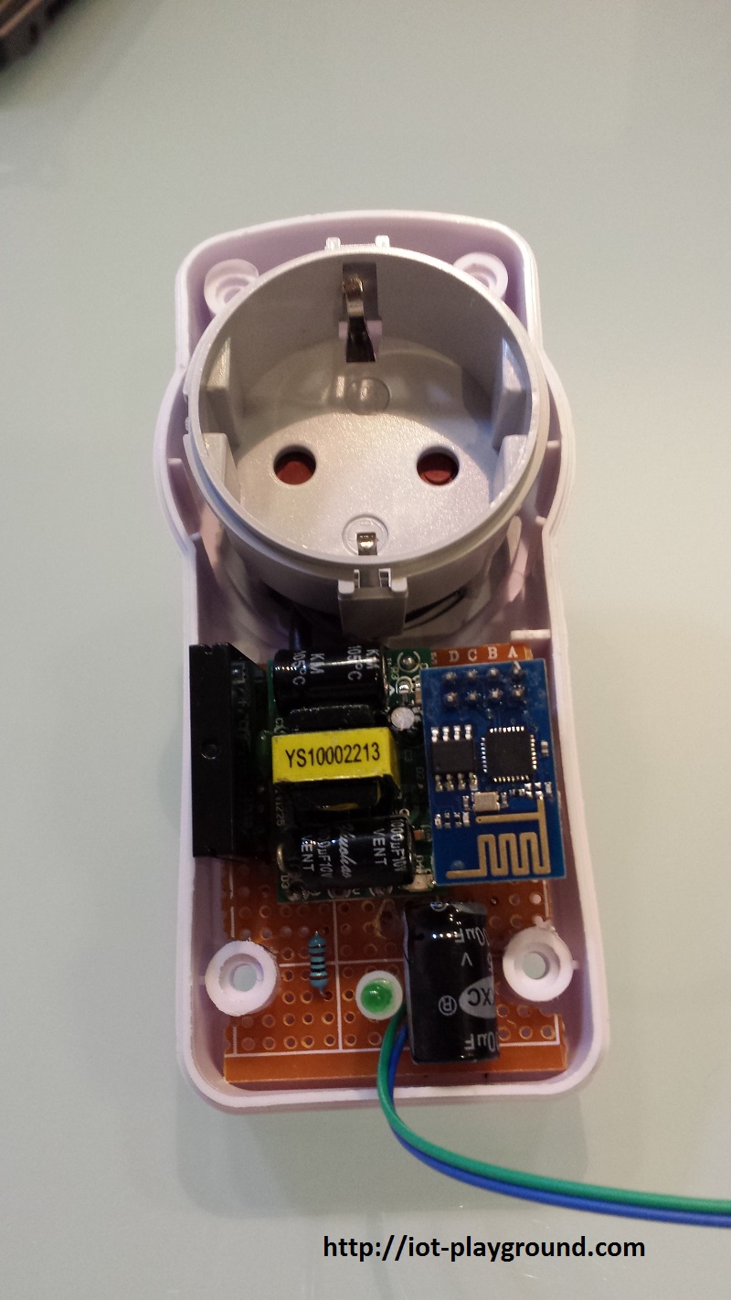
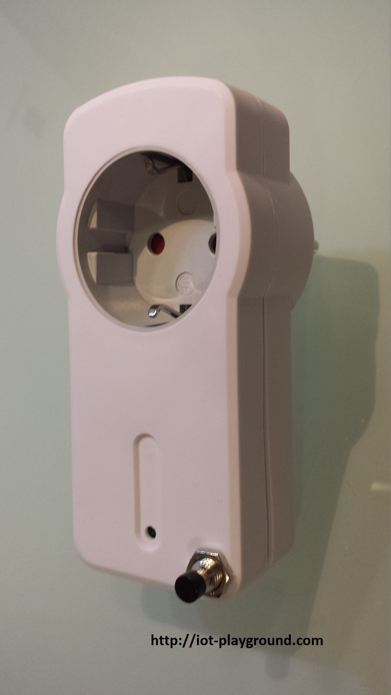
Finished ESP8266 internet controlled switch
Materials
- ESP8266 WiFi relay module
| ESP8266 Wifi Relay Module | |
$7.9  | |
$7.04  |
| ESP8266 Network Relay WIFI Module | |
| $7.19 | |
| $7.25 |
- ESP8266 WiFi module
| ESP8266 ESP-01 Serial WIFI Wireless Transceiver Module | |
| $2.11 | |
| $17.00 |
| ESP8266 ESP-03 Serial WIFI Wireless Transceiver Module | |
| $2.07 | |
| $2.15 |
| ESP8266 ESP-12 Serial WIFI Wireless Transceiver Module | |
| $2.06 | |
| $1.75 |
| ESP8266 ESP-05 Serial WIFI Wireless Transceiver Module | |
| $1.88 |
| ESP8266 ESP-07 Serial WIFI Wireless Transceiver Module | |
| $2.18 | |
| $1.88 |
| ESP8266 Lua Nodemcu WIFI Network Development Board | |
| $7.43 | |
| $2.65 |
- Solid State Relay 2A 240V
| Solid State Relay 2A 240V | |
| $0.99 | |
| $1.13 |
- 3.3V 600mA AC-DC step down module
| 3.3V 600mA AC-DC step down module | |
| $1.99 | |
| $1.85 |
- Push Button switch
| 10Pcs Push Button switch | |
| $1.61 | |
| $1.80 |
- NPN Transistor TO-92 2N2222
| 100Pcs NPN Transistor TO-92 2N2222 | |
| $1.01 | |
| $0.90 |
- Electrolytic capacitor
| 210Pcs 25 Value 0.1uF-220uF Electrolytic Capacitors Assortment Kit Set | |
| $3.36 | |
| $6.52 |
- Resistor
| 400X 0.25w 1/4w Metal Film Resistor Pack Kit 1% 20 Value Each 20 Pcs 10 ~ 1M ohm | |
| $1.88 | |
| $5.50 |
See buying guide at the end of tutorial for details.
EasyIoT Cloud configuration
No EasyIoT Cloud configuration is needed, just register to EasyIoT Cloud service. You will need username and password to access your internet switch on WEB application or in Android application. Switch will be automatically added to EasyIoT Cloud and will be visible in WEB interface or in Android application after power on.
Program
Program is written in Arduino ESP8266 IDE. See Arduino ESP8266 IDE tutorial how to connect ESP8266 module to computer to upload program. Program can be downloaded from our GitHub. You will also need MQTT client library. Add this library to library folder in Arduino IDE. Program uses EasyIoT Cloud MQTT API.
In program change following lines, to set access point username and password and EasyIoT username and password:
#define AP_SSID "xxx"
#define AP_PASSWORD "xxx"
#define EIOTCLOUD_USERNAME "xxx"
#define EIOTCLOUD_PASSWORD "xxx"
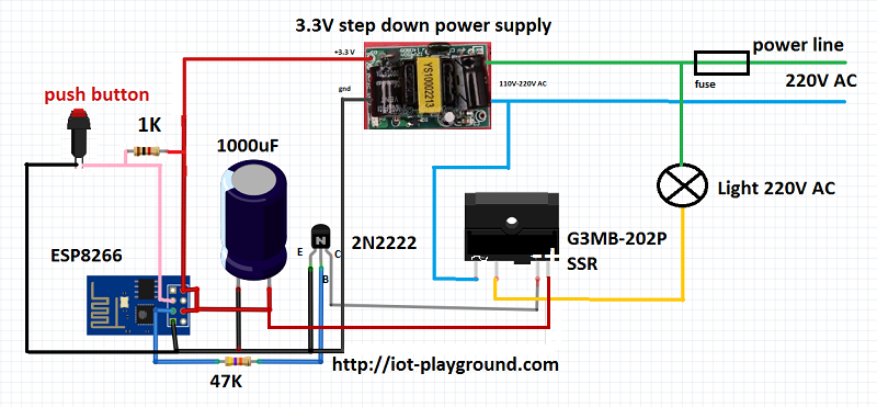
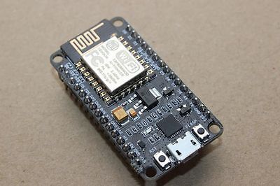
Hardware
In our case we use ESP8266 01, but you can use any other type of ESP8266. GPIO2 is connected to NPN transistor to control SSR. Max current for our type of solid state relay is 2A - this is suitable for room light and not for applications which consume more power - for example heater.
For power supply we use 3.3V step down module. It's very important to add 1000uF capacitor to 3.3V power line - in our case switch didn't work if we skip this capacitor.
GPIO0 is connected to push button for local control of internet switch.
After power on, switch will be automatically added to EasyIoT Cloud and it will be visible in WEB interface or Android application.
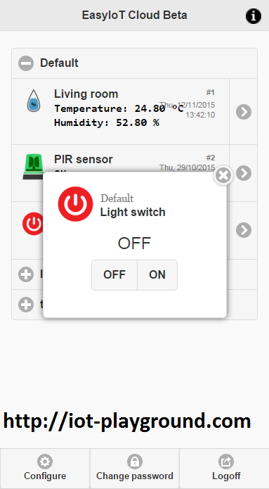
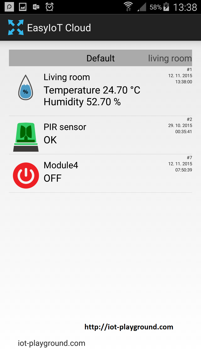
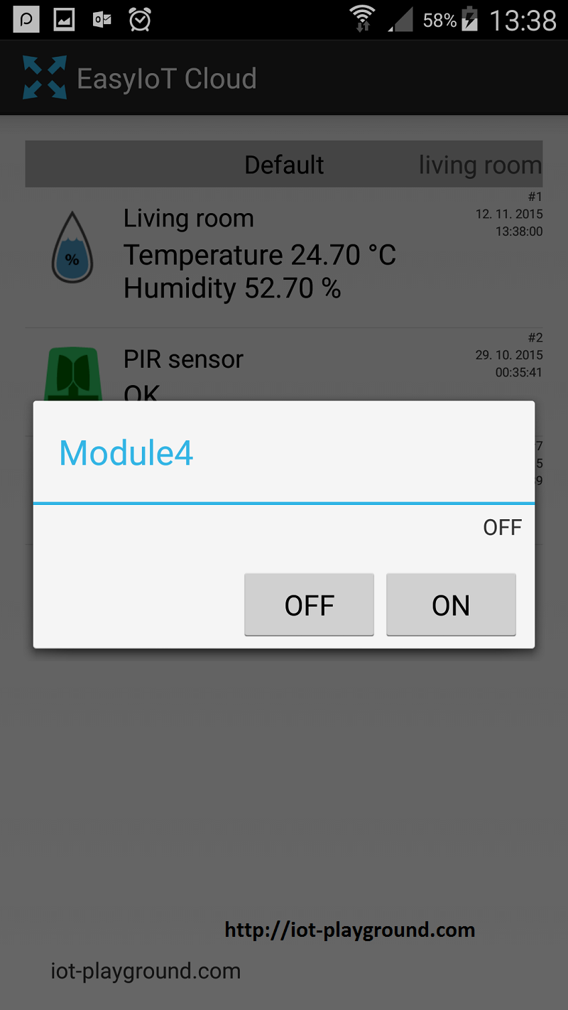
You can manually rename name of your switch and group in EasyIoT Cloud configuration to suits your need.
This tutorial is obsolete. Use updated version ESP8266 internet connected switch (EasyIoT Cloud MQTT API V1) - improved.
See more tutorials at http://iot-playground.com/build
Buying guide
To support this site and EasyIoT framework development please buy in our store.


Comments
Its working fine there is no troubles. But I need some modification.
How can I assign 2 GPIO's (GPIO0 and GPIO2) as OUTPUT, hence I don't want local switch
http://iot-playground.com/blog/2-uncategorised/85-easyiot-cloud-module-configuration
I'm trying to add a second relay to the ESP8266 module.
My approach is to add a "Sensor.Parameter2" but in the EasyIOT cloud the module only have one on/off switch.
It looks like things are working but I don't understand how I can add the second switch in the EeayIOT cloud (module view)
Some screenshots are attached
I have a problem with this sketch.
When I turn ESP8266, I do not add switch to EasyIoT Cloud
Appears my new WIFI network (ESP.XXXX) that blocks my router.
Where can I mistaken?
Cannot find a clue in the Materials list ...
Please help!
Franz
Hi, try to add 100nF
capacitor parallel with push buttonto transistor B and ground. I guess this can lower noise. Report if it works.And please share your PCB.
Any ideas how to modify the circuit to eliminate such disturbances?
What can cause it?
The GPIO is pulled up using 1k resistor.
Please help. If something is unclear i can answer any questions.
I can also share the wiring diagram and pcb layout i created for this project.
RSS feed for comments to this post