- Posts: 4
- Thank you received: 0
esp8266-01 and GPIO2 for 5v rele activation
9 years 3 weeks ago #3833
by fsitios
esp8266-01 and GPIO2 for 5v rele activation was created by fsitios
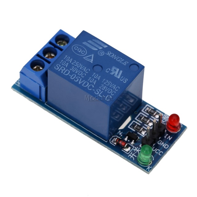
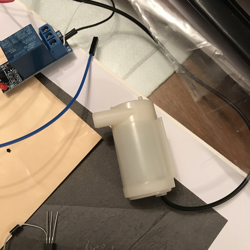
HI, I want to control a single channel 5v relay (see photo) of an ESP8266-01 to turn on and off a mini 3V water pump (see picture). To control the relay I have to use the GPIO0 port of the ESP because the GPIO2 I am using it to measure soil moisture. The general idea is to watering the flowerpot when the soil is dry.
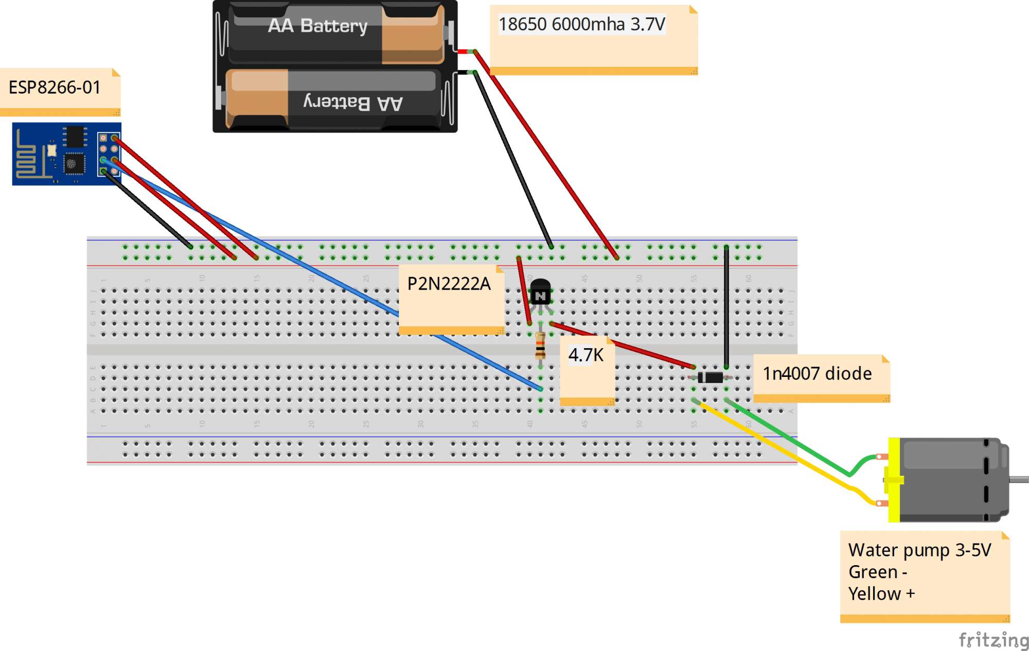
I have everything connected according to the attached diagram (sorry I did it by hand but I am not an electronic). So, when the pump starts(the relay is acticated) the whole circuit hungs (all the lights of all the components goes on). I also have another problem, to boot the ESP I have to disconnect the GPIO0 so that it drops in normal mode and then reconnect it to make the scheme work.
My questions are, what should I do to stabilize the circuit and make it work?, and what can I do to avoid disconnect and connect manually the GPIO0 all the time to start in "normal" mode?
Here are the details of the water pump:
DC Voltage:2.5-6V
Maximum lift:40-110cm / 15.75"-43.4"
Flow rate:80-120L/H
Outside diameter of water outlet: 7.5mm / 0.3"
Inside diameter of water outlet: 4.7mm / 0.18"
Diameter:Approx. 24mm / 0.95"
Length:Approx. 45mm / 1.8"
Height:Approx. 33mm / 1.30"
Material:engineering plastic
Driving mode: brushless dc design, magnetic driving
Continuous working life of 500 hours
Relay details:
Modulo Rele 5V - Simple Inversor - 250V 10A
Thanks in advance!!
Fernando
Please Log in or Create an account to join the conversation.
9 years 3 weeks ago #3834
by EasyIoT
ESP8266-01 are very unpractical, because pin limitations. I suggest you to use different ESP8266 - ESP8266-12 for example.
Replied by EasyIoT on topic esp8266-01 and GPIO2 for 5v rele activation
fsitios wrote: HI, I want to control a single channel 5v relay (see photo) of an ESP8266-01 to turn on and off a mini 3V water pump (see picture). To control the relay I have to use the GPIO0 port of the ESP because the GPIO2 I am using it to measure soil moisture. The general idea is to watering the flowerpot when the soil is dry.
I have everything connected according to the attached diagram (sorry I did it by hand but I am not an electronic). So, when the pump starts(the relay is acticated) the whole circuit hungs (all the lights of all the components goes on). I also have another problem, to boot the ESP I have to disconnect the GPIO0 so that it drops in normal mode and then reconnect it to make the scheme work.
My questions are, what should I do to stabilize the circuit and make it work?, and what can I do to avoid disconnect and connect manually the GPIO0 all the time to start in "normal" mode?
Here are the details of the water pump:
DC Voltage:2.5-6V
Maximum lift:40-110cm / 15.75"-43.4"
Flow rate:80-120L/H
Outside diameter of water outlet: 7.5mm / 0.3"
Inside diameter of water outlet: 4.7mm / 0.18"
Diameter:Approx. 24mm / 0.95"
Length:Approx. 45mm / 1.8"
Height:Approx. 33mm / 1.30"
Material:engineering plastic
Driving mode: brushless dc design, magnetic driving
Continuous working life of 500 hours
Relay details:
Modulo Rele 5V - Simple Inversor - 250V 10A
Thanks in advance!!
Fernando
ESP8266-01 are very unpractical, because pin limitations. I suggest you to use different ESP8266 - ESP8266-12 for example.
The following user(s) said Thank You: fsitios
Please Log in or Create an account to join the conversation.
9 years 3 weeks ago #3837
by fsitios
Replied by fsitios on topic esp8266-01 and GPIO2 for 5v rele activation
Thank you for the tip about the ESP8266-12.
What about the second issue?. I am using a P2N2222 transistor to switch off and on the DC, but I am getting this stuff in the debug terminal when the DC is turned on or off. I connected the GPIO0 to the transistor Base pin. Is this a correct circuit, isnt it?. Or what am I missing here?
Regards,
Fernando
What about the second issue?. I am using a P2N2222 transistor to switch off and on the DC, but I am getting this stuff in the debug terminal when the DC is turned on or off. I connected the GPIO0 to the transistor Base pin. Is this a correct circuit, isnt it?. Or what am I missing here?
ets Jan  8 2013,rst cause:4, boot mode:(3,0)

wdt reset
load 0x4010f000, len 1384, room 16
tail 8
chksum 0x2d
csum 0x2d
v09f0c112
~ld
Regards,
Fernando
Please Log in or Create an account to join the conversation.
9 years 2 weeks ago #3843
by btidey
Replied by btidey on topic esp8266-01 and GPIO2 for 5v rele activation
Main reason for getting these wdt resets is power supply issues.
You need to have a good well decoupled stable 3.3V supply for the ESP8266. You may well be getting a significant spike when the relay switches which is getting through to the ESP8266 supply.
According to schematic you are deriving the 3.3V from 5V via converter which is OK but you should put a decoupling capacitor at the ESP8266 end. I typically use a 220uF 6.3V one.
Please Log in or Create an account to join the conversation.
9 years 2 weeks ago #3844
by EasyIoT
Debug mode is for ESP8266 NODE MCU boards. You can not use DEBUG together with ESP8266-01 and this circuit. And power supply is important as @btidey mention.
Replied by EasyIoT on topic esp8266-01 and GPIO2 for 5v rele activation
fsitios wrote: Thank you for the tip about the ESP8266-12.
What about the second issue?. I am using a P2N2222 transistor to switch off and on the DC, but I am getting this stuff in the debug terminal when the DC is turned on or off. I connected the GPIO0 to the transistor Base pin. Is this a correct circuit, isnt it?. Or what am I missing here?
ets Jan  8 2013,rst cause:4, boot mode:(3,0)

wdt reset
load 0x4010f000, len 1384, room 16
tail 8
chksum 0x2d
csum 0x2d
v09f0c112
~ld
Regards,
Fernando
Debug mode is for ESP8266 NODE MCU boards. You can not use DEBUG together with ESP8266-01 and this circuit. And power supply is important as @btidey mention.
The following user(s) said Thank You: fsitios
Please Log in or Create an account to join the conversation.
9 years 2 weeks ago #3847
by fsitios
Replied by fsitios on topic esp8266-01 and GPIO2 for 5v rele activation
Thank you so much for your answer. Only one question, Which is "the end" of the ESP8266 you are mentioning?.
Thanks!
Thanks!
Please Log in or Create an account to join the conversation.
Time to create page: 0.729 seconds
Forum latest
- No posts to display.