- Posts: 5
- Thank you received: 2
ESP8266 WiFi relay switch (Arduino IDE)
10 years 6 months ago - 10 years 6 months ago #2781
by f8vpe
Replied by f8vpe on topic ESP8266 WiFi relay switch (Arduino IDE)
For the second one (the first link is dead) you have to supply +5V and - (negative) to the relay and the IN and - (negative) to the ESP On the other hand you may use a solid state relay, you may connect it directly between the negative and the port of the ESP (or inversed)The drive power on the port is 12mA, a relay board needs 0.75 mA, the solid state needs 6.5 mA so this should not give any problems.
http://www.ebay.com/itm/24V-380V-40A-250V-SSR-40-DA-Solid-State-Relay-Module-3-32V-DC-To-AC-/201414937205
Last edit: 10 years 6 months ago by f8vpe.
Please Log in or Create an account to join the conversation.
10 years 6 months ago #2783
by sueche
Replied by sueche on topic ESP8266 WiFi relay switch (Arduino IDE)
I've just checked and both links I posted are viable.
And yes, I am supplying 5V and ground(-) to the relay, and IN and ground(-) to the ESP but it can't drive the relay - that's why I used this schematic with the PN2222 transistor.
Nevertheless, thanks for the suggestion using a solid state relay - I'll give it a try.
If I could avoid using a transistor it would be better/simpler.
Please Log in or Create an account to join the conversation.
10 years 6 months ago #2793
by f8vpe
Replied by f8vpe on topic ESP8266 WiFi relay switch (Arduino IDE)
That's our difference of view, the ESP should not drive the relais at all, only the optocoupler who's asking less than 1mA.
Perhaps you have to cut a wire, on the two and four relays boards you will find a jumper to do so.
I have a ESP running with a four relayboard attached to it without any problem.
There should be another issue there, the resistor between 5V and 3v3 !
When the ESP have to deliver current to the opto the 3V3 could be lowered. My advise is to add a voltage regulator.
Succes, Robert.
Please Log in or Create an account to join the conversation.
10 years 6 months ago - 10 years 6 months ago #2795
by sueche
Replied by sueche on topic ESP8266 WiFi relay switch (Arduino IDE)
Hello Robert,
I got your point.Feeding the optocoupler through the ESP and the relay coil from the power source itself. I can do that with the 30A relay - if you take a look at the relay boards there is a jumper for providing different power source to the relay coil, than the one for the optocoupler.
But this is only for the 30A relay, 10A relay doesn't have such jumper - the relay coil and the optocoupler are sharing the same power supply. (I am using only 1-relay boards).
For the purpose of explanation, here's my breadboard (sorry about the pictures' quality - 5M camera on the phone):
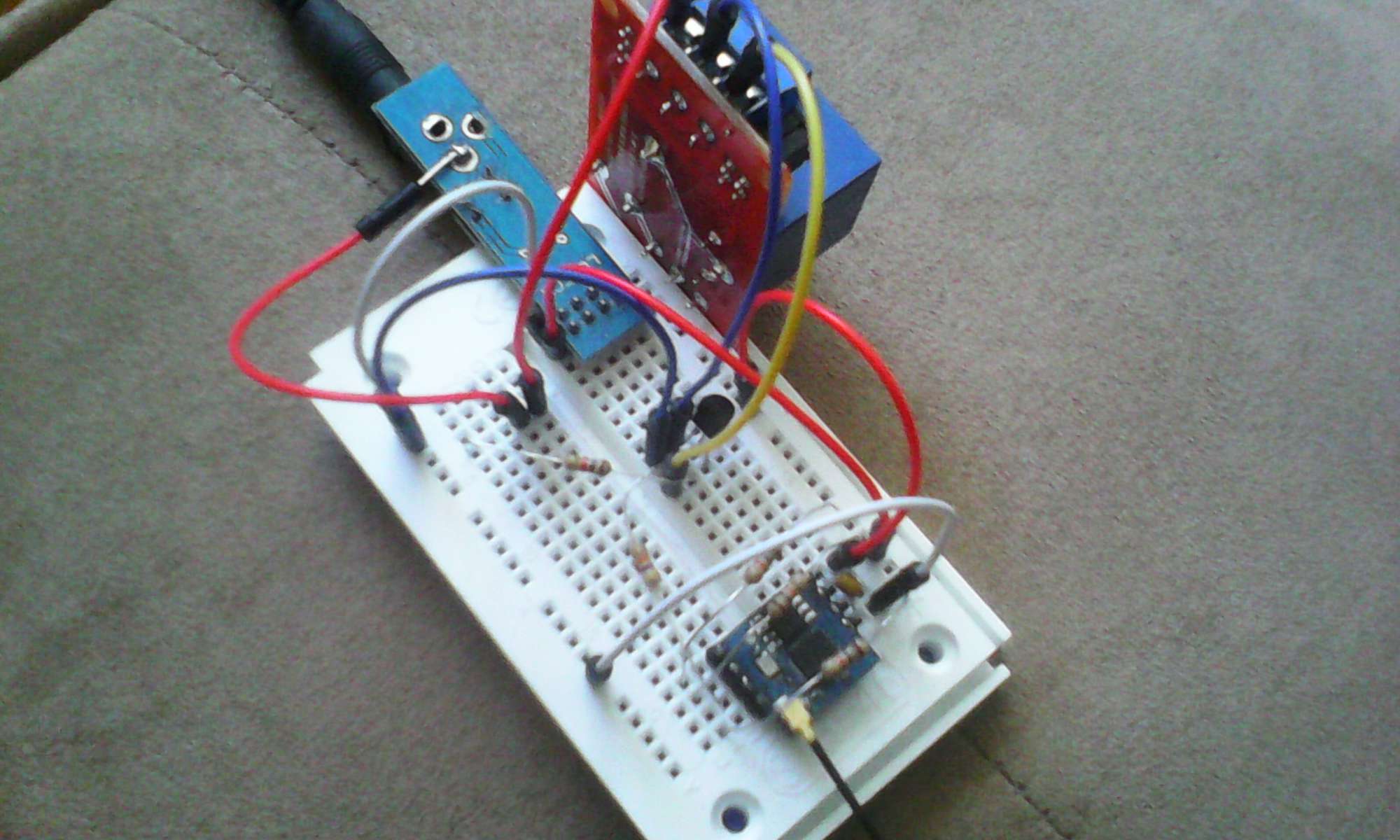
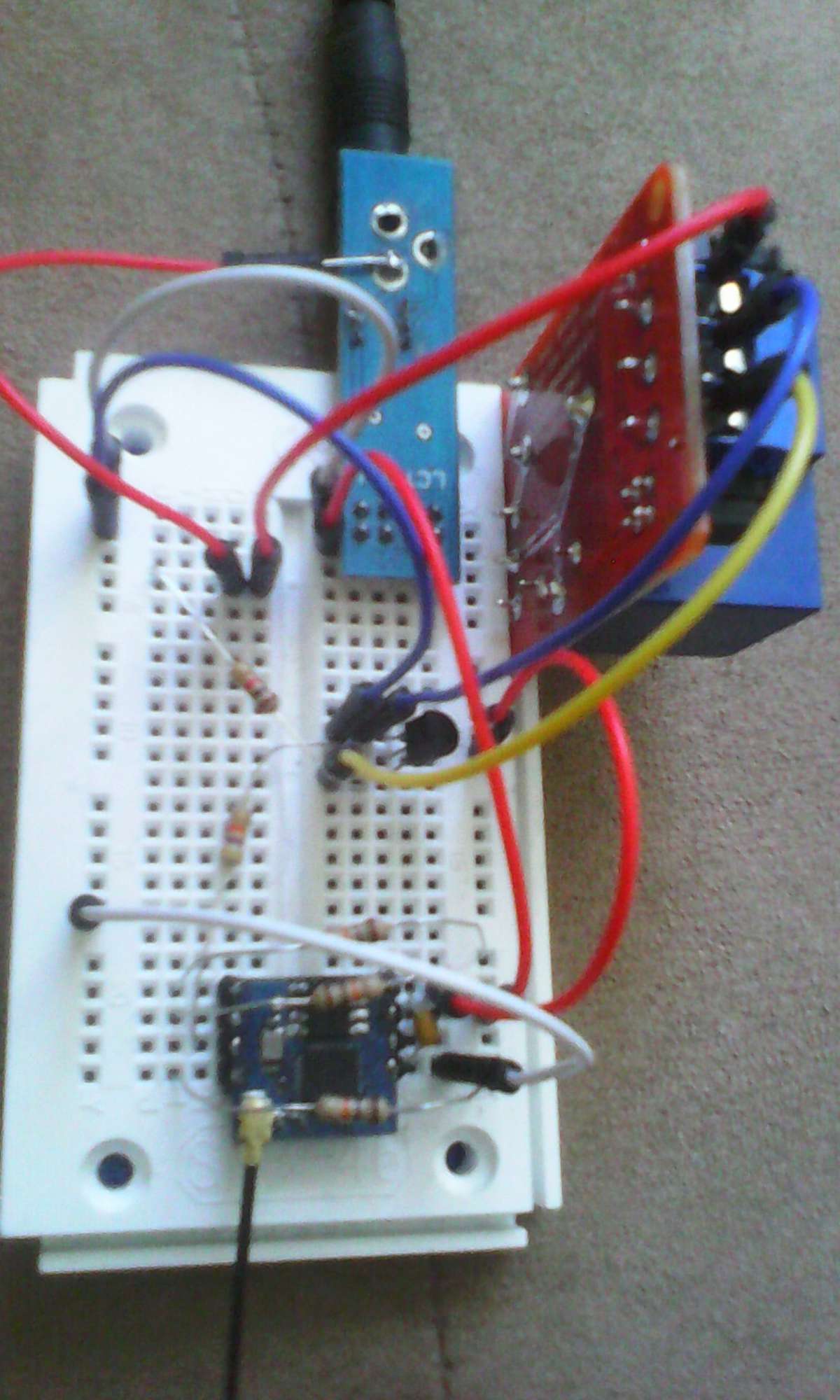
I am using a voltage regulator which is about 1A - it powers the ESP. I feed the relay board before the regulator with 5V directly from the power supply - 1A. The relay board, ESP and the power supply (voltage regulator) are sharing common ground. The rest is as it is on the initial schematic I posted.
I got your point.Feeding the optocoupler through the ESP and the relay coil from the power source itself. I can do that with the 30A relay - if you take a look at the relay boards there is a jumper for providing different power source to the relay coil, than the one for the optocoupler.
But this is only for the 30A relay, 10A relay doesn't have such jumper - the relay coil and the optocoupler are sharing the same power supply. (I am using only 1-relay boards).
For the purpose of explanation, here's my breadboard (sorry about the pictures' quality - 5M camera on the phone):
I am using a voltage regulator which is about 1A - it powers the ESP. I feed the relay board before the regulator with 5V directly from the power supply - 1A. The relay board, ESP and the power supply (voltage regulator) are sharing common ground. The rest is as it is on the initial schematic I posted.
Last edit: 10 years 6 months ago by sueche.
Please Log in or Create an account to join the conversation.
10 years 6 months ago #2797
by f8vpe
Replied by f8vpe on topic ESP8266 WiFi relay switch (Arduino IDE)
You've got it, I know most of the single relays do have common power, you may change the board but for that price you may use a 30A instead. Also handy is the solid state, more reliable but a little bit bigger. There is a 25A and a 40A. The advantage is that you don't need the 5V. anymore.
Bye, Robert.
Bye, Robert.
Please Log in or Create an account to join the conversation.
10 years 5 months ago #2922
by Manan
Replied by Manan on topic ESP8266 WiFi relay switch (Arduino IDE)
i m trying to make a wifi enabled relayswitch with help of iotcloud, following this tutorial :
iot-playground.com/blog/2-uncategorised/..._cloud_configuration
the problem that i m facing is :
while pasting the arduino code in my arduino ide and compling it, it is giving me multiple errors, even though i have successfully downloaded and added the library required for esp8266, mqqt and eeprom
link from where i have downloaded the mqtt library :
github.com/iot-playground/EasyIoT-Cloud/...r/libraries/esp-mqtt
the errors are :
sketch_feb15b:64: error: 'loadConfig' was not declared in this scope
loadConfig();
^
sketch_feb15b:95: error: 'macToStr' was not declared in this scope
clientName += macToStr(mac);
^
sketch_feb15b:105: error: 'myConnectedCb' was not declared in this scope
myMqtt.onConnected(myConnectedCb);
^
sketch_feb15b:106: error: 'myDisconnectedCb' was not declared in this scope
myMqtt.onDisconnected(myDisconnectedCb);
^
sketch_feb15b:107: error: 'myPublishedCb' was not declared in this scope
myMqtt.onPublished(myPublishedCb);
^
sketch_feb15b:108: error: 'myDataCb' was not declared in this scope
myMqtt.onData(myDataCb);
^
sketch_feb15b:120: error: 'waitOk' was not declared in this scope
waitOk();
^
sketch_feb15b:154: error: 'saveConfig' was not declared in this scope
saveConfig();
^
C:\Users\Manan Mehta\Documents\Arduino\sketch_feb15b\sketch_feb15b.ino: In function 'void loop()':
sketch_feb15b:211: error: 'saveConfig' was not declared in this scope
saveConfig();
^
exit status 1
'loadConfig' was not declared in this scope
Please help me to solve it
Please Log in or Create an account to join the conversation.
Time to create page: 0.348 seconds
Forum latest
- No posts to display.