In this tutorial we will show how to build door/window sensor only with ESP8266 and NodeMCU(LUA) - without Arduino. We will use nice EasyIoT interface to display door/windows status on our phone, tablet or desktop computer.
ESP8266 NodeMcu
First step when building this sensor is to upload correct firmware to our ESP8266 module. We will use node NodeMCU firmware. This firmware is capable of executing LUA script. Latest NodeMCU firmware can be download here NodeMCU. Read ESP8266 firmware update tutorial for instructions how to update ESP8266 firmware.
Next we will add virtual door/window sensor to EasyIoT server. You can download EasyIoT server (Windows or Raspberry Pi version) on EasyIoT server download page.
Material
- ESP8266 module
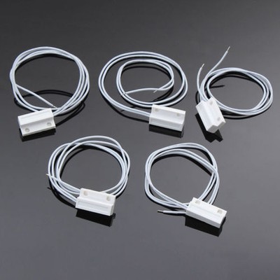
- Reed relay
- 100nF ceramic capacitor
See buying guide at the end of tutorial.
EasyIoT server configuration
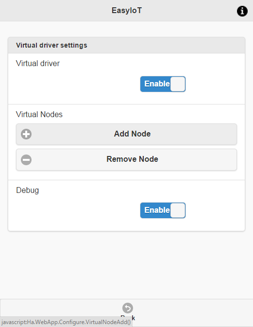
Go to Configure->Drivers->Virtual driver and press button Add node. Virtual driver must be enabled.
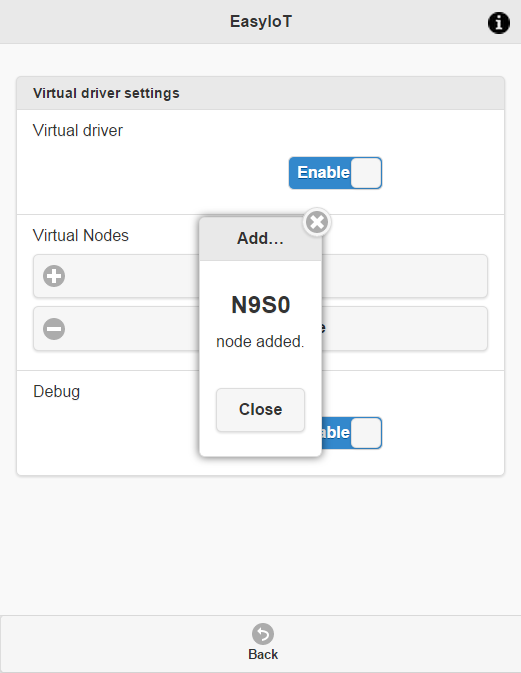
Remember node address. In this case is N9S0.
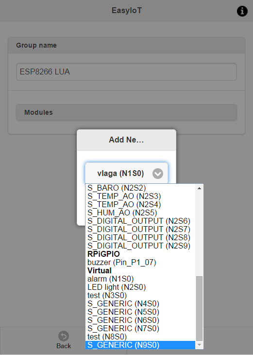
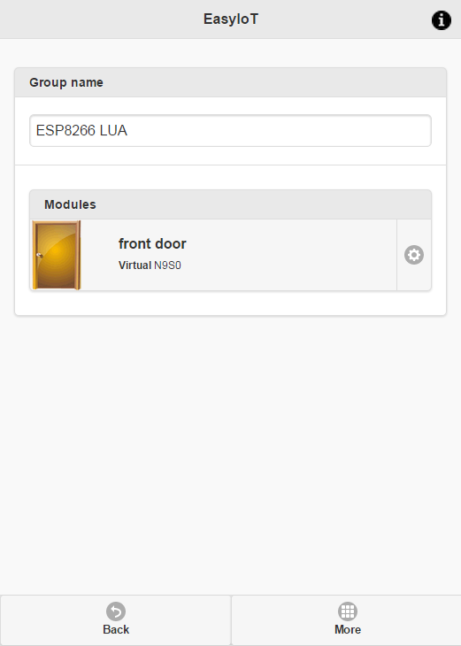
Then go back in Groups and modules and newly added module (address N9S0).
Then name senosr and change type to Door/Window(Di) sensor.
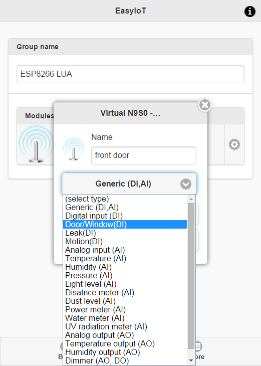
After you add sensor it should be like this.
Upload LUA program
To upload LUA program to ESP8266 we need LUAloader. It can be found here. If you just updated firmware don't forget to disconnect GND wire connected to GPIO0 - we do not need it any more.
LUA program can be found on GitHub. There are two files: init.lua and lua_easyiot_doorwindow.lua. Download both files and correct AP and AP password in init.lua. In file lua_easyiot_doorwindow.lua correct server IP address EasyIoT username and password and node address. In our case node address is N9S0, but in your case can be different.
Change this line in init.lua:
wifi.sta.config("AP","password")
and this in lua_easyiot_doorwindow.lua:
easyiot_username = "admin"
easyiot_password = "test"
easyiot_server = "192.168.1.5"
easyiot_node_address = "N9S0"
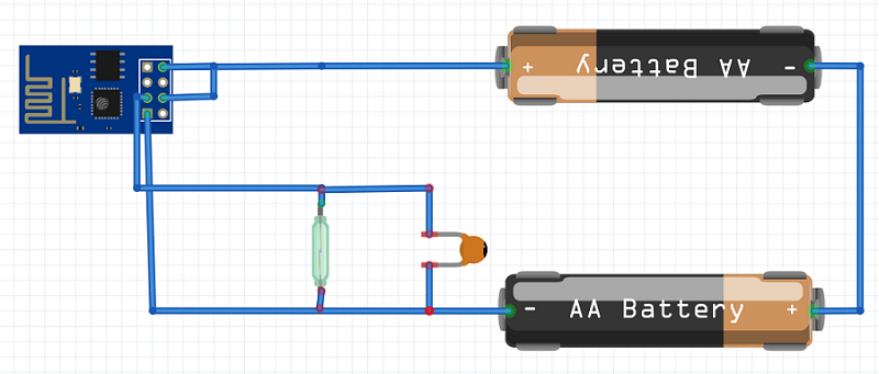
Connecting
Now we just need to connect wires. Add magnetic reed relay switch and 100nF capacitor for debouncing and two AA batteries. See buying guide for details.
Check also EasyIoT Cloud ESP8266 door/window sensor.
See more tutorials at http://iot-playground.com/build
Buying guide
To support this site and EasyIoT framework development please buy in our store.
 $3.19
$3.19 $7.00
$7.00


Comments
For example, I have a door closed/open sensor and I'd like to add another sensor for the lock of the same door. Then I would know that door is "closed and locked" or door is "closed and unlocked".
Forget the battery... you must use a power supply and an esp different from ESP-01 or it doesn't work on reboot if reed is closed.
Thanks,
Gilson
Ok to connect gpio2 to reed and reed to +3.3v
Ok to modify code :
gpio.mode(4,gpio.INT,gpio.PULLDOWN)
BUT IS ALSO NECESSARY TO MODIFY :
command = 'ControlOff'
if (status == 0) then
command = 'ControlOn'
end
(and not status == 1 !!!)
1) connect reed1 to +3.3v
2) connect gpio2 to +3.3v
3 connect reed2 to gnd
this produce a loop of "1" status....
1) connect reed1 to +3.3v
2) connect gpio2 to reed2
this produce a NULL status... nothing appear when i close or open reed
gpio.mode(4,gpio.INT,gpio.PULLDOWN) line modified
obviously in pull-up mode with gpio2 to reed1 and gnd to reed2 works perfectly, but when reset with closed door it doesn't start correct as you discovered.
Please can you explain better how to fix it ?
Dario
if i connect reed to 3.3v coming out from AMS1117 and to GPIO2 it doesn't work, obviously code modified.
Try to debug it in breadboard but when open and close reed do nothing in this way.....
GPIO2, I will fix comment.
Thanks in advance
Dario
Quoting Super User:
Later I've discovered one little detail about ESP8266. While power up GPIO2 must be connected to VCC to start in correct mode. In my test case it happened that door was open and GPIO2 was on VCC. If you start this example with door closed it won't work because ESP8266 wont start int correct mode. There are two solutions:
-connect reed relay and capacitor to VCC and GPIO2. That way GPIO2 will be always connected to VCC at startup. Also correct line gpio.mode(4,gpio.INT,gpio.PULLUP) to gpio.mode(4,gpio.INT,gpio.PULLDOWN)
-use different ESP8266 model and connect reed relay to different GPIO pin. Also correct program to work with different GPIO.
RSS feed for comments to this post