In this tutorial we will show how to build WiFi internet controlled switch connected to EasyIoT Cloud with 4 relays and one ESP8266. We will use Arduino IDE to program ESP8266
This internet connected switch is simplified version of ESP8266 internet connected switch. Program code is simplified - it's not plug and play, with hard coded configuration, but it uses 4 relays instead of just one. You can easy extend program to control more relays with single ESP8266. Relays can be controlled from anywhere in the world - you just need internet connection.
Devices can be controlled over EasyIoT Cloud interface or native Android Application.
WARNING!! You will play with LIVE MAINS!! Deadly zone!!
If you don't have any experience and are not qualified for working with MAINS power I will not encourage you to play around!
Do NOT use it without proper Knowledge about MAINS circuits !
Do NOT use it without a proper FUSE on MAINS line!
Max current for solid state in this tutorial is 2A - suitable for room light only.
Contents
3. EasyIoT Cloud configuration
Introduction
Materials
-ESP8266 WiFi module
| ESP8266 ESP-12 Serial WIFI Wireless Transceiver Module | |
$2.06  |
| ESP8266 ESP-07 Serial WIFI Wireless Transceiver Module | |
| $2.18 |
| ESP8266 Lua Nodemcu WIFI Network Development Board | |
| $7.43 |
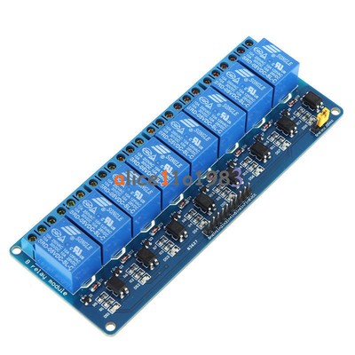
-Relay module
| 1 Channel Isolated 5V Relay Module | |
| $1.34 |
| 2 Channel 5V Relay Module With optocoupler | |
| $1.46 |
| 4 Channel 5V Relay Module With optocoupler | |
| $2.46 |
| 8 Channel 5V Relay Module With optocoupler | |
| $4.82 |
-3.3V power supply
| 5pcs 3.3V regulator module 800mA | |
| $1.12 |
-4.7K Resistor
| 400X 0.25w 1/4w Metal Film Resistor Pack Kit 1% 20 Value Each 20 Pcs 10 ~ 1M ohm | |
| $1.88 |
-NPN Transistor TO-92 2N2222
| 100Pcs NPN Transistor TO-92 2N2222 | |
| $1.01 |
See buying guide at the end of tutorial for details.
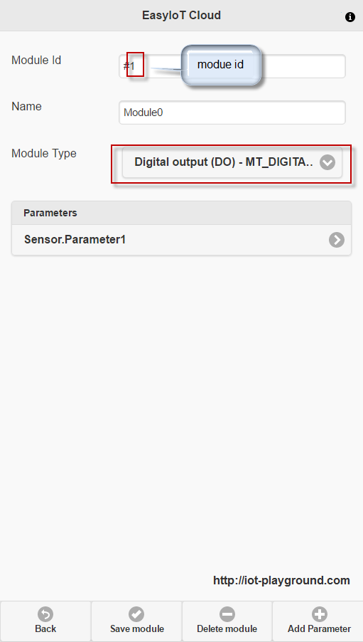
EasyIoT Cloud configuration
First register to EasyIoT Cloud service. We will add DO modules manually. Go to Configure->Modules. If there are demo modules you do not need delite them all. Then press button Add Module. Change module type to Digital Output DO (MT_DIGITAL_OUTPUT) and save module. It's important to remember module ID. If this is your first module in your configuration, module ID should be 1. Next add more DO modules - in our case 3 more, but it can be dependent on your program and number of relays.
Program
Program is written in Arduino ESP8266 IDE. See Arduino ESP8266 IDE tutorial how to connect ESP8266 module to computer to upload program. Program can be downloaded from our GitHub. You will also need MQTT client library. Add this library to library folder in Arduino IDE. Program uses EasyIoT Cloud MQTT API.
In program change following lines EasyIoT Cloud username and password:
#define EIOTCLOUD_USERNAME "xxx"
#define EIOTCLOUD_PASSWORD "xxx"
Also set up your WiFi access point name and password:
#define AP_SSID "xxx"#define AP_PASSWORD "xxx"
If you use different DO pins than default D0,D1,D2,D3 change those pins.
In program also change module ID to correspond to those in user interface:
#define MODULE_ID_1 1
#define MODULE_ID_2 2
#define MODULE_ID_3 3
#define MODULE_ID_4 4
The easiest way to test program is to use ESP8266 LUA node MCU board. Just connect it to USB port and you can test program. If you use this board you can also uncomment #define DEBUG to see debug messages. Flash button on ESP8266 board will work as button to manually change switch state. Onboard LED displays switch state.
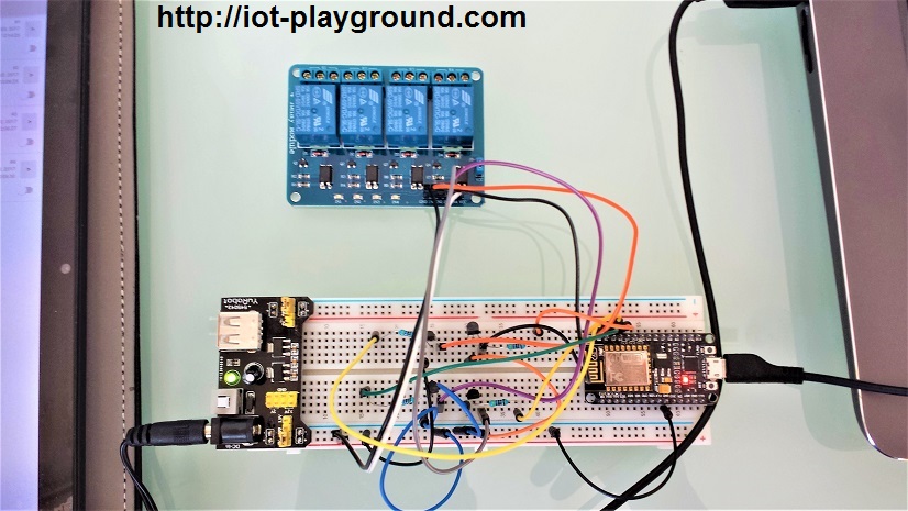
Hardware
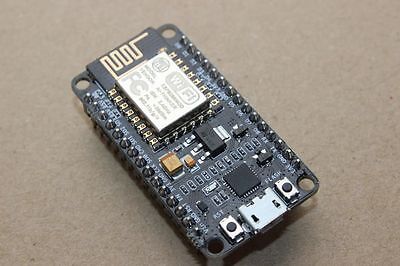
In our case we use NODEMCU ESP8266, but you can use any other type of ESP8266 with all pins exposed. In our program we connect D0,D1, D2 and D3 to circuit which controls relays. Relays are using 5V ESP8266 is using 3.3V. To connect 3.3V ESP8266 to 5V relay module we use one NPN transistor 2N2222. Connection is shown below:
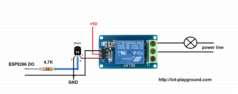
Ground is common, ESP8266 is on 3.3V, relay module is on 5V. You can use relay module with more relays (2,4,8).
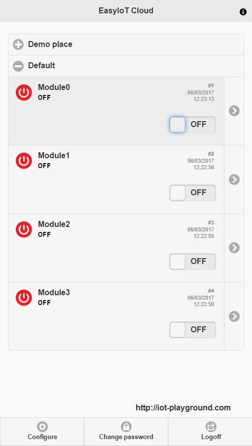
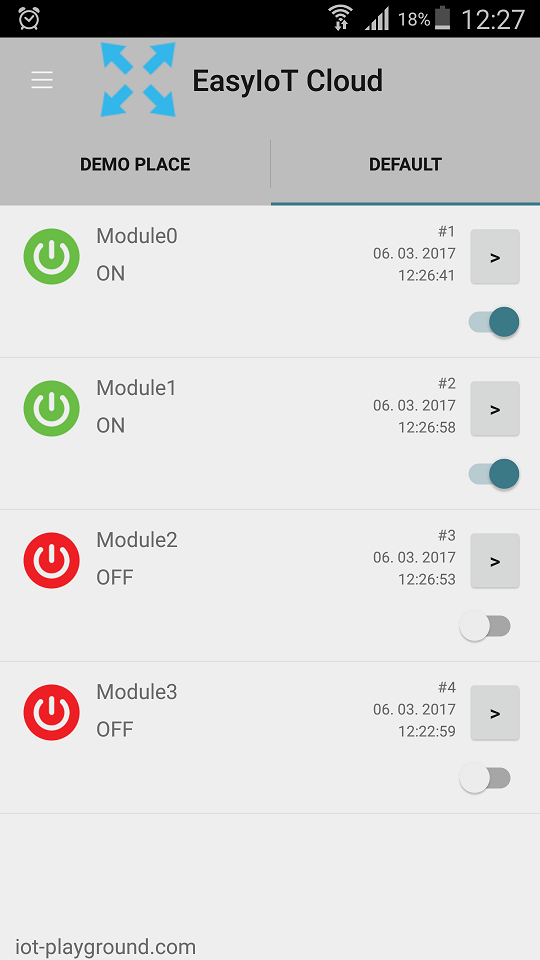
Modules can be manually renamed in EasyIoT Cloud configuration to suits your need.
See more tutorials at http://iot-playground.com/build
Buying guide
To support this site and EasyIoT framework development please buy in our store.


Comments
i can't upload because :
MQTT myMqtt("", EIOT_CLOUD_ADDRESS, 1883);
MQTT does not name a type
does not produce any debug value's even on single line of serial print
code run up to subscribe not further how to debug?
esp8266-01
No I used generic ESP-8266. I will give that a try.
Did you select NodeMCU board in Boards manager?
'D0' was not declared in this scope
RSS feed for comments to this post