In this tutorial we will show how to build ESP8266 relay without Arduino in ESP8266 Arduino IDE. We will use EasyIoT server for web interface.
Please see also EasyIoT Cloud version of ESP8266 relay switch ESP8266 internet connected switch (EasyIoT Cloud MQTT API V1) - improved.
We already show how to build ESP8266 Arduino relay switch. In this example we will skip Arduino and program ESP8266 directly.
Materials
- ESP8266 module
| ESP8266 ESP-01 Serial WIFI Wireless Transceiver Module | |
$2.11  | |
$17.00  |
| ESP8266 ESP-03 Serial WIFI Wireless Transceiver Module | |
| $2.07 | |
| $2.15 |
| ESP8266 ESP-12 Serial WIFI Wireless Transceiver Module | |
| $2.06 | |
| $1.75 |
| ESP8266 ESP-05 Serial WIFI Wireless Transceiver Module | |
| $1.88 |
| ESP8266 ESP-07 Serial WIFI Wireless Transceiver Module | |
| $2.18 | |
| $1.88 |
| ESP8266 Lua Nodemcu WIFI Network Development Board | |
| $7.43 | |
| $2.65 |
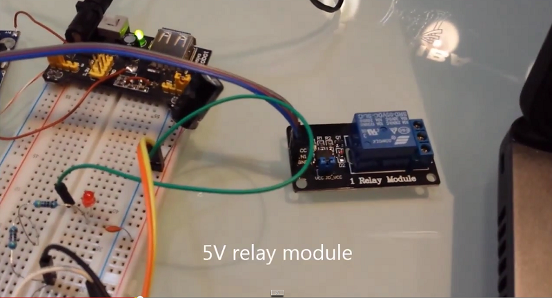
- 5V Relay
| 1 Channel Isolated 5V Relay Module | |
| $1.34 | |
| $1.12 |
- 2N2222 - NPN transistor
| 100Pcs NPN Transistor TO-92 2N2222 | |
| $1.01 | |
| $0.90 |
- 1K resistor
- 47K resistor
| 400X 0.25w 1/4w Metal Film Resistor Pack Kit 1% 20 Value Each 20 Pcs 10 ~ 1M ohm | |
| $1.88 | |
| $5.50 |
- 5V Power suply
| 5V 2A Charger Micro USB | |
| $2.43 | |
| $3.40 |
- AMS1117 3.3V
| 5pcs 3.3V regulator module 800mA | |
| $1.12 | |
| $1.56 |
See buying guide at the end for details.
Program
We will need Arduino IDE. See ESP8266 Arduino IDE blink example how to correctly program ESP8266 with Arduino IDE. When we connect wires, we upload our program. Program is basic WiFiWebServer example but can be also found on GitHub. Correct AP name and password in following lines:
const char* ssid = "your-ssid";
const char* password = "your-password";
After you set proper AP name and password compile and upload program. When you finish with program upload remove GND wire from GPIO0 pin to enter in program execution mode. Restart our module and keep FT232RL FTDI USB to TTL Serial+Adapte connected to Arduino tool. In Serial Monitor check if ESP module connects to AP. If connection is successful you will also see IP address of ESP8266. Remember this IP address.
Connection
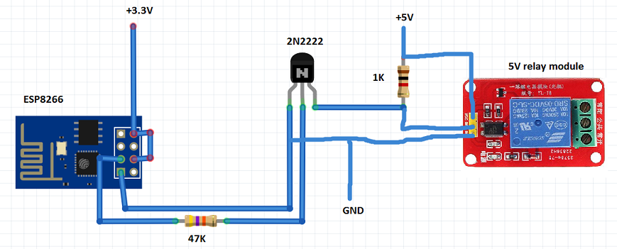
Connect ESP8266 GPIO2 pin to 5V relay module IN. Because relay module operats on 5V and ESP8266 operate on 3.3V we will use 2N2222 NPN transistor to shift levels. Grund is common for 5v and 3.3V. On relay we can connect different devices.
EasyIoT server configuration
In EasyIoT server Web interface we add new module in Virtual driver. Set module type Digital output (DO). Read tutorial how to add new module. Remember module address, beacuse it's important.
Next we add automation program. Automation program will call our ESP8266 module when we press button in Web interface. Read EasyIoT server automation tutorial how to add program in EasyIoT server.
You do not need to set CRON, just add following program. Correct ESP8266_IP_ADDRESS to your module address and module address MODULE_ADDRESS visible in Web configuration.
const String ESP8266_IP_ADDRESS = "192.168.1.6";
const String MODULE_ADDRESS = "N12S0";
/*
This code is running one time when program is enabled
*/
public void Setup()
{
System.Diagnostics.Process.Start("CMD.exe","");
EventHelper.ModuleChangedHandler((o, m, p) =>
{
Console.WriteLine(m.Domain +" "+ m.Address + " in program id "+ Program.ProgramId.ToString()+ " property "+ p.Property + " value " + p.Value);
if (m.Domain == "Virtual" && m.Address == MODULE_ADDRESS && p.Property == "Sensor.DigitalValue")
sendCommand(p.Value);
return true;
});
}
/*
This code is running periodicaly when program is enabled.
Cron job detirmine running period.
*/
public void Run()
{
}
private void sendCommand(string value)
{
sendToServer("/gpio/"+value);
}
private void sendToServer(String message)
{
try
{
//Console.WriteLine("TCP client command:" + message);
Int32 port = 80;
System.Net.Sockets.TcpClient client = new System.Net.Sockets.TcpClient( ESP8266_IP_ADDRESS, port);
Byte[] data = System.Text.Encoding.ASCII.GetBytes(message);
System.Net.Sockets.NetworkStream stream = client.GetStream();
stream.Write(data, 0, data.Length);
// Close everything.
stream.Close();
client.Close();
}
catch(Exception e)
{
Console.WriteLine(e.StackTrace);
}
}
Enable program and go in EasyIoT Web interface. Now you can control relay with switch.
See also tutorial ESP8266 internet connected switch (EasyIoT Cloud MQTT API).
See more tutorials at http://iot-playground.com/build
Please see also EasyIoT Cloud version of ESP8266 relay switch ESP8266 internet connected switch (EasyIoT Cloud MQTT API V1) - improved.
Buying guide
To support this site and EasyIoT framework development please buy in our store.


Comments
but i think it 's a little slow to change the switch,and this method is very strange.
is there any direct control method by mqtt driver or other driver example ?
i founded there is not a mqtt api for EasyIoT server MQTT driver, i used arduino IDE for ESP8266 without arduino,hope somebody can help me ,best wishes!
When I turn the power on the ESP seems to hang (doenst start) and the Relay keeps pulling.
If I turn the power off and disconnect the line between the ESP and the Resistor everything works OK after the power is turned on. Also now when I re-connect the wire I can control the Relay with ESP.
Does anyone have any idea what might be the issue? Thanks in advance.
http://www.aliexpress.com/item/2-two-channel-relay-module-relay-expansion-board-with-optocoupler-3-3V-and-5V-compatible/32305097030.html?spm=2114.01020208.3.95.hfkNsm&ws_ab_test=searchweb201556_1,searchweb201644_1_79_78_77_82_80_62_81_61,searchweb201560_3
You can add physical buttons to the system. This is framework, and you can build your own system and you decide how you will use it.
For more questions please join community forum.
RSS feed for comments to this post