This tutorial will show how to modify Arduino Pro Mini into low power Arduino.
As we seen in previous article it's not good idea to use step up regulator to power low power sensors. NRF24L01+ can operate down to 1.8V. If we modify Arduino to operate on 1.8V and use low voltage sensor, then we can create low power sensor.
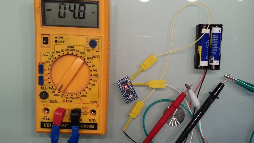
Arduino Pro Mini is very suitable base for small sensors. But if we measure power consumption of standard Arduino we will see, that power consumption is quite big. For test purpose we use empty program:
void setup() {
}
void loop() {
}
3V 8MHz Arduino Pro Mini consumes 4.8mA.
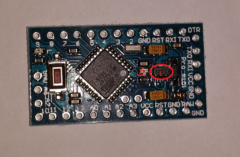
4.8mA is way too high for low power sensor. To lower current consumption we remove regulator and power LED.
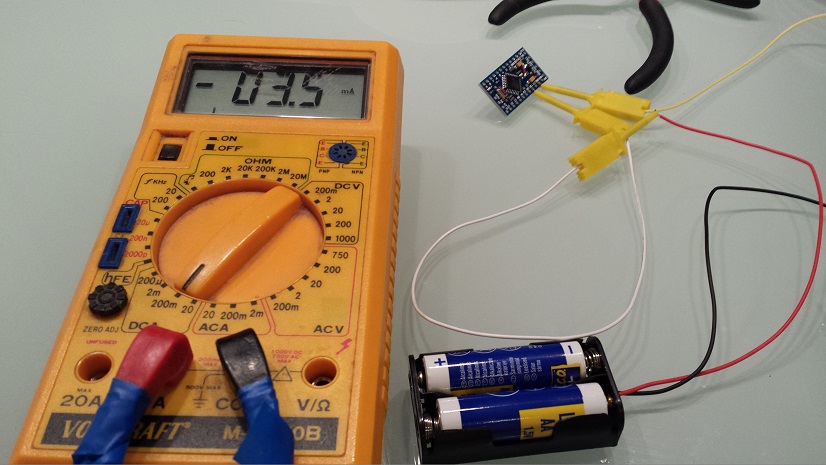
After this modification power consumption is 3.5mA.
Arduino Pro Mini now runs at 8 MHz on external crystal. If we look in Atmel823 datasheet we will see that it is safe to operate at 8MHz down to 2.4V.
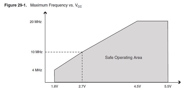
If we want to operate at 1.8V we should change frequency to 4MHz (see picture above). To do that we should change crystal. Other way is to switch to internal oscillator at 8MHz and divide frequency by 8. That way it will operate at 1MHz.
To do that we burn fuses:
avrdude -c usbtiny -p m328p -U lfuse:w:0x62:m
and disable brown-out:
avrdude -c usbtiny -p m328p -U efuse:w:0x07:m
You can program fuses with other Arduino board. Here is tutorial how to do it.
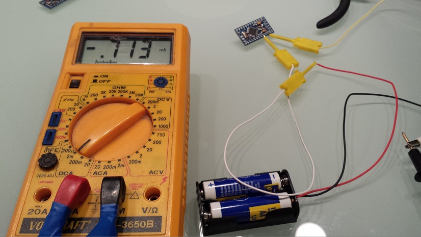
If we measure current consumption now we will see 0.731mA.
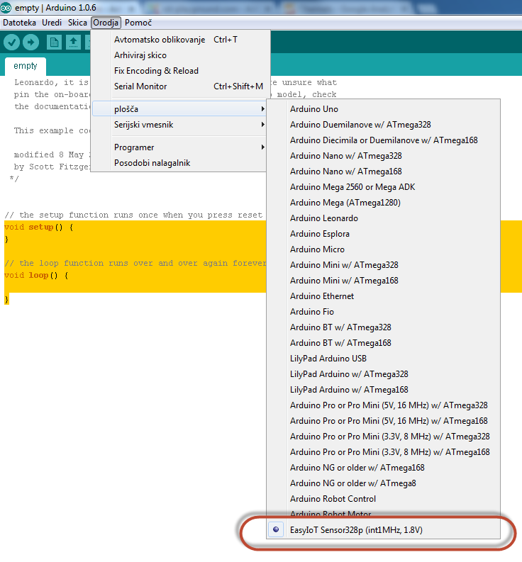
Now we need to add new board in Adruino IDE. Go to Arduino\hardware\arduino\boards.txt and add:
 s328o1.name=EasyIoT Sensor328p (int1MHz, 1.8V)
 s328o1.upload.protocol=arduino
 s328o1.upload.maximum_size=30720
 s328o1.upload.speed=7200
 s328o1.bootloader.low_fuses=0x62
 s328o1.bootloader.high_fuses=0xda
 s328o1.bootloader.extended_fuses=0x06
 s328o1.bootloader.path=atmega
 s328o1.bootloader.file=ATmegaBOOT_168_atmega328_pro_8MHz.hex
 s328o1.bootloader.unlock_bits=0x3F
 s328o1.bootloader.lock_bits=0x0F
 s328o1.build.mcu=atmega328p
 s328o1.build.f_cpu=1000000L
 s328o1.build.core=arduino
 s328o1.build.variant=standard
If you add correctly you should see:
Now we can upload program in our low power Arduino Pro Mini. In sleep mode that modified Arduino consumes about 6μA (μA not mA).
In next post we will show how to create low power sensor which can run up to 10 years on two AA batteries.
See more tutorials at http://iot-playground.com/build
Buying guide
To support this site and EasyIoT framework development please buy in our store.

 $2.59
$2.59 $3.99
$3.99


Comments
avrdude -C "C:\Program Fil
es (x86)\Arduino\hardware\tools\avr/etc/avrdude.conf" -v -patmega328p -cstk500v1
-PCOM7 -b19200 -U efuse:w:0x07:m
avrdude -C "C:\Program Fil
es (x86)\Arduino\hardware\tools\avr/etc/avrdude.conf" -v -patmega328p -cstk500v1
-PCOM7 -b19200 -U lfuse:w:0x62:m
I'm doing something different... and it's working now !! GREAT !!!
I compile the sketch in .hex an then, from my linux command line using my usbasp I flash .hex file to arduino low power, testing with blink sketch (and not using the arduino IDE, so forgot the boards.txt file) with this command :
avrdude -P /dev/ttyUSB0 -c usbasp -p m328p -B250 -U flash:w:Blink.cpp.eightanaloginputs.hex
Working as expected, blinking led 13, with 2 AA used batteries (2.49V total).
Kindly Regards.
Cheers from Madrid (Spain)
Thank you !
pro.menu.cpu.1MHzatmega328.upload.speed=19200
set CONF="C:\Program Files (x86)\Arduino\hardware\tools\avr/etc/avrdude.conf"
avrdude -C %CONF% -v -patmega328p -carduino -PCOM4 -b57600
By the way, i was using my Arduino UNO as an ISP. That was not mentioned above and I was using a FTDI. That won't work based on many many hours of failure.
Please, take a look of my boards.txt :
## Arduino Pro or Pro Mini (1.8V, 1 MHz) w/ ATmega328
## --------------------------------------------------
pro.menu.cpu.1MHzatmega328=ATmega328 (1.8V, 1 MHz)
pro.menu.cpu.1MHzatmega328.upload.maximum_size=30720
pro.menu.cpu.1MHzatmega328.upload.maximum_data_size=2048
pro.menu.cpu.1MHzatmega328.upload.speed=7200
pro.menu.cpu.1MHzatmega328.bootloader.low_fuses=0x62
pro.menu.cpu.1MHzatmega328.bootloader.high_fuses=0xDA
pro.menu.cpu.1MHzatmega328.bootloader.extended_fuses=0x06
pro.menu.cpu.1MHzatmega328.bootloader.file=atmega/ATmegaBOOT_168_atmega328_pro_8MHz.hex
pro.menu.cpu.1MHzatmega328.build.mcu=atmega328p
pro.menu.cpu.1MHzatmega328.build.f_cpu=1000000L
Thank you !!
I asume that in normal mode (atmega328 3.3V, 8Mhz) the upload.speed parameter is 57600. So if I use atmega328 1.8V, 1Mhz, I divide the upload.speed parameter by 8 so results 7200, right ?
avrdude: stk500_recv(): programmer is not responding
avrdude: stk500_getsync() attempt 1 of 10: not in sync: resp=0x00
avrdude: stk500_recv(): programmer is not responding
avrdude: stk500_getsync() attempt 2 of 10: not in sync: resp=0x00
avrdude: stk500_recv(): programmer is not responding
avrdude: stk500_getsync() attempt 3 of 10: not in sync: resp=0x00
Any help ? The fuses are set and the boards.txt is updated.
Thanks.
drive.google.com/file/d/0B2jB-FlIrSJjak9CY18zSjZ0Slk/view?usp=sharing
I ran this with a 3.7v LS 14500 battery and during the sleep cycles it consumed 40uA (0.04mA) with a NRF24L01+ connected.
RSS feed for comments to this post