In this tutorial we will show how to create ESP8266 WiFi relay switch with ESP8266 module and Arduino. You can use relay switch to remotly control more than one device (as many as you have free Arduino digital ports). You can also combine relay switch with other sensors. We will use ESP8266 EasyIoT library.
Materials
See buying guide at the end of tutorial.
-ESP8266 WiFi module
| ESP8266 ESP-01 Serial WIFI Wireless Transceiver Module | |
$2.11  | |
$17.00  |
| ESP8266 ESP-03 Serial WIFI Wireless Transceiver Module | |
| $2.07 | |
| $2.15 |
| ESP8266 ESP-12 Serial WIFI Wireless Transceiver Module | |
| $2.06 | |
| $1.75 |
| ESP8266 ESP-05 Serial WIFI Wireless Transceiver Module | |
| $1.88 |
| ESP8266 ESP-07 Serial WIFI Wireless Transceiver Module | |
| $2.18 | |
| $1.88 |
-Arduino Pro Mini 8Mhz, 3.3V
| 3.3V 8Mhz Arduino Pro Mini | |
| $2.05 | |
| $1.78 |
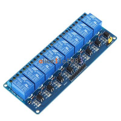
-5V Relay module
| 1 Channel Isolated 5V Relay Module | |
| $1.34 | |
| $1.12 |
-5V power supplay
| 5V 2A Charger Micro USB | |
| $2.43 | |
| $3.40 |
-3.3V power supply (see datasheet)
| 10Pcs AMS1117-3.3 LM1117 3.3V 1A SOT-223 Voltage Regulator | |
| $0.99 | |
| $1.22 |
-EasyIoT server on Raspberry Pi (see download page)
| RASPBERRY PI 3 - Model B. 1GB RAM | |
| $41.99 | |
| $39.96 |
-WiFi network (WiFi router)
Connect wires
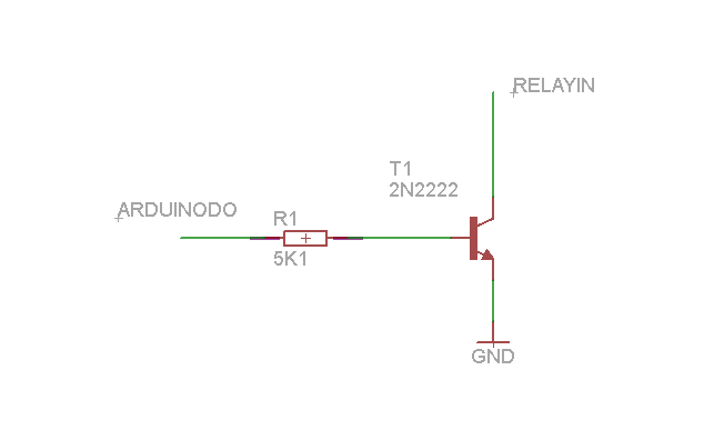
Connect Arduino Pro Mini and ESP8266 module. See conenct ESP8266 and Arduino tutorial how to do this. Then we need to connect relay module. Relay module has 5V power supply so we connect VCC to 5V power supply and GND is common to 5V and 3.3V. Next we connect relay module to IN to digital pin on Arduin board. Because relay module is powered by 5V and Arduino on 3.3V we will add transistor transistor 2N2222 and 10K resistor between modules. In our case we will use Arduino pin 13. You can select other pin or connect more relays to more Arduino pins. Don't forget to correct Arduino program if you use different pins.
After we connect wires we will program Arduino. Arduino ESP8266 WiFi Relay switch is available at GitHub. Don't forget to set correct access point and password and EasyIoT server IP address in Esp8266EasyIoTConfig.h.
Add relay node to EasyIoT server
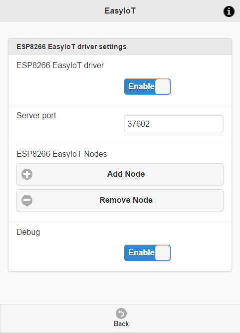
Go to in Web browser and enter EasyIoT server IP address. After logging in go to Configuration->Drivers->ESP8266 EasyIoT driver and enable driver. Then click "Add node" and switch on relay node.
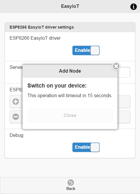
After 15s you should see newly added module(no timeout message).
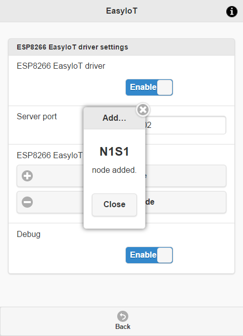
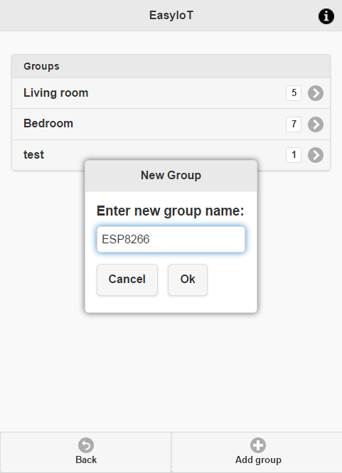
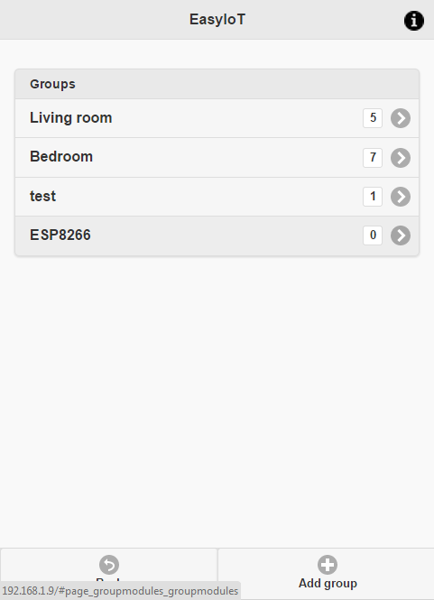
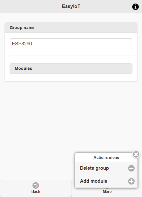
Now add new module to group to see it on front page.
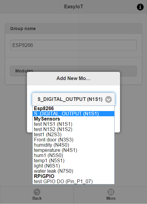
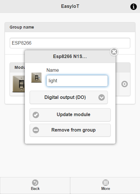
Name module.
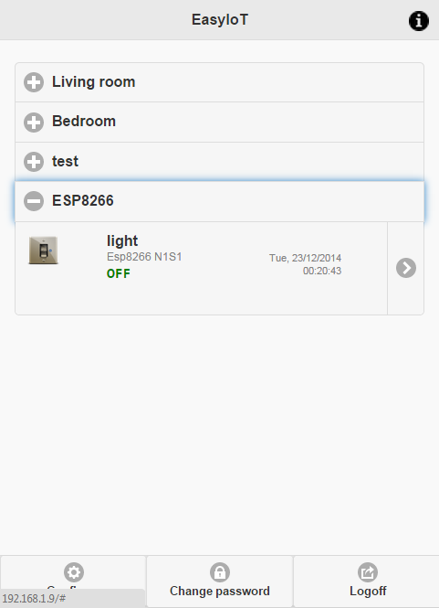
If you done everything correctly you should see relay node on front page.
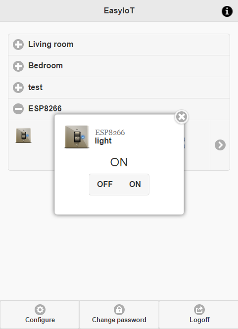
Click on switch control in web browser and test ESP8266 WiFi relay module.
Check also ESP8266 Cloud relay tutorial.
See more tutorials at http://iot-playground.com/build
Buying guide
To support this site and EasyIoT framework development please buy in our store.


Comments
Nice project... almost all clear but I'm new in electronic subject... I don't understand this:
"Then we need to connect relay module. Relay module has 5V power supply so we connect VCC to 5V power supply and GND is common to 5V and 3.3V. Next we connect relay module to IN to digital pin on Arduin board. Because relay module is powered by 5V and Arduino on 3.3V we will add transistor transistor 2N2222 and 10K resistor between modules"
Could you explain it... You know "for dummies"... My realy bord couldn't be controled by 3V3 GPIO...
Please help ;)
yes, see http://iot-playground.com/build for more details...
Computer is usually on the same network as ESP8266.
Am getting error...:(
Awaiting with anticipation...
RSS feed for comments to this post