- Posts: 65
- Thank you received: 13
nodeMCU dimmer/switch/temp.sensor without arduino
8 years 11 months ago - 8 years 11 months ago #1611
by ArneiO
Replied by ArneiO on topic nodeMCU dimmer/switch/temp.sensor without arduino
@cdj: I think this is a good choice of FET for the application. I see no reason that it should not work. You wrote that the power supply is 6A? For 10 m LED stripes? That sounds too little. How are you driving the FET? 5V or 3.3V GPIO? Can you show us the circuit diagram?
Last edit: 8 years 11 months ago by ArneiO.
Please Log in or Create an account to join the conversation.
8 years 11 months ago - 8 years 11 months ago #1617
by cdj
No, no wait.
This is specs of led strip (FOR 1 STRIP), :
Working input Voltage : 12VDC , 6A
Working power : 72W/5M
I use a 20A power supply for each groups of strip (3 strip for 3.5mt each one)
This is the link for software :
http://iot-playground.com/forum/lua-programming/102-nodemcu-dimmer-switch-temp-sensor-without-arduino
This is code for dimmer, just adapt for two dimmer...
Circuit is very simple, driven direct from esp8266 in nodemcu/lua. GND of supply to mosfet SOURCE, gpio0 to GATE and LED GND to DRAIN.
Same with gpio2
Don't really know why doesn't work with big load
Replied by cdj on topic nodeMCU dimmer/switch/temp.sensor without arduino
ArneiO wrote: @cdj: I think this is a good choice of FET for the application. I see no reason that it should not work. You wrote that the power supply is 6A? For 10 m LED stripes? That sounds too little. How are you driving the FET? 5V or 3.3V GPIO? Can you show us the circuit diagram?
No, no wait.
This is specs of led strip (FOR 1 STRIP), :
Working input Voltage : 12VDC , 6A
Working power : 72W/5M
I use a 20A power supply for each groups of strip (3 strip for 3.5mt each one)
This is the link for software :
http://iot-playground.com/forum/lua-programming/102-nodemcu-dimmer-switch-temp-sensor-without-arduino
This is code for dimmer, just adapt for two dimmer...
Circuit is very simple, driven direct from esp8266 in nodemcu/lua. GND of supply to mosfet SOURCE, gpio0 to GATE and LED GND to DRAIN.
Same with gpio2
Don't really know why doesn't work with big load
Last edit: 8 years 11 months ago by cdj.
Please Log in or Create an account to join the conversation.
8 years 11 months ago #1621
by ArneiO
Replied by ArneiO on topic nodeMCU dimmer/switch/temp.sensor without arduino
@cdj: That sounds fine, providing the voltage coming from the ESP is high enough. Did you try switching on the FET manually, with a 3.3V signal directly to the gate? It is in general recommended to use a serial resistor to the FET gate to limit inrush current, but I think there is enough output impedence on the ESP for this not to be a problem (in any case, it is not the reason for your problem).
If it works with low load it could sound as if the FET is not properly turned ON. It could be worth while to use a transistor to drive it, switching the 12V to the gate. You would then be sure it is fully ON.
If it works with low load it could sound as if the FET is not properly turned ON. It could be worth while to use a transistor to drive it, switching the 12V to the gate. You would then be sure it is fully ON.
Please Log in or Create an account to join the conversation.
8 years 11 months ago #1626
by cdj
Replied by cdj on topic nodeMCU dimmer/switch/temp.sensor without arduino
Solved !!! GND of ESP must be in common with SOURCE GND....It works perfectly... but also this node is not very stable.... :
Thanks for helping
Thanks for helping
Please Log in or Create an account to join the conversation.
- BerniApple
- Offline
- New Member
-

Less
More
- Posts: 2
- Karma: -1
- Thank you received: 0
8 years 2 months ago #2817
by BerniApple
Thanks a lot man, everything its ok but i have only one question. How can i use and control separately both GPIO0 and GPIO2 of the Esp8266 1?
Replied by BerniApple on topic nodeMCU dimmer/switch/temp.sensor without arduino
Dennis wrote: Hello folks,
in another thread there was the idea to use esp8266 running nodeMCU firmware, to create easyIoT node without arduino, instead directly using the esp8266's GPIO pins to control a LED dimmer, here's link to the other thread: iot-playground.com/forum/suggestion-box/...6-only-needed/unread
User "VasilijHCN" wrote some easyIoT automation program for connecting to a virtual node, to be able to send TCP commands to a nodeMCU with mosFETs attached for LED dimming.
I then further developed this code and extended it to also switch on/off things, so one can use nodeMCU as well for a simple relay node in easyIoT, and published results in said thread - goal was to create one nodeMCU "init.lua" script which can be used as standalone node in easyIoT, for sensor readings and as switch/dimmer, and all without use of arduino, only esp8266 module.
Meanwhile I have done some more development on that code, as well as on the init.lua script running on the esp8266.
- now the switching function uses a separate TCP command, you can send command to nodeMCU in form of "SWITCH1=1" (turns GPIO0 on ) or "SWITCH2=0" (turns off GPIO02) - no pwm duty cycle anymore when switching, gives better relay debounce
- I also added a temperature readout command to the nodeMCU ini.lua, now we can send "GETTEMP" to nodeMCU and get a reply containing temperature as decimal value (atm just a static value is returned; I still need to implement proper sensor readout in init.lua, as soon as I can find a spare Ds18b20 sensor for testing)
So now, we can directly control IO pins of a ESP8266 running nodeMCU (either control with PWM, or just plain digital outputs), and we can read sensor values from it - all from easyIoT.
How does it work?
- load nodeMCU firmware 0.9.4 onto esp8266 module, see this blog post for details on how to do it: blog.quindorian.org/2015/01/esp8266-wifi...mer-part-3-of-x.html
- upload the following "init.lua" script onto your nodeMCU Esp8266 (replace SSID and PASSWORD wifi params with your own):after uploading this code as "init.lua", you need to connect module to your wifi, then note its IP address, and restart the module. Both (setting wifi parameters and loading the script onto esp8266) can be done with the following tool: esp8266.ru/esplorer/pwm.setup(3, 1000, 000) pwm.setup(4, 1000, 000) pwm.start(3) pwm.start(4) LED1_current=000 LED1_target=000 LED2_current=000 LED2_target=000 SWITCH1_state = 0 SWITCH2_state = 0 Fadetime1=1000 Fadetime2=1000 Stepcounter1=0 PosStepcounter1=0 DimTimer1=0 Stepcounter2=0 PosStepcounter2=0 DimTimer2=0 wifi.setmode(wifi.STATION) wifi.sta.config("MYSSID","MYPASSWORD") srv=net.createServer(net.TCP) srv:listen(43333,function(conn) conn:on("receive",function(conn,payload) print("Input: "..payload) if string.find(payload,"GETTEMP") then print("Received temperature request") conn:send("25.33") elseif string.find(payload,"SWITCH1") then SWITCH1_state=tonumber(string.sub(payload, 9) ) print("Received SWITCH1 target Value: "..SWITCH1_state) if SWITCH1_state == 1 then pwm.setduty(3, 1023) LED1_current = 1023 elseif SWITCH1_state == 0 then pwm.setduty(3, 0) LED1_current = 0 end elseif string.find(payload,"SWITCH2") then SWITCH2_state=tonumber(string.sub(payload, 9) ) print("Received SWITCH2 target Value: "..SWITCH2_state) if SWITCH2_state == 1 then pwm.setduty(4, 1023) LED2_current = 1023 elseif SWITCH2_state == 0 then pwm.setduty(4, 0) LED2_current = 0 end elseif string.find(payload,"LED1") then LED1_target=tonumber(string.sub(payload, 13) ) print("Received LED1 Target Value: "..LED1_target) Stepcounter1=(LED1_target)-(LED1_current) if (Stepcounter1) < 0 then PosStepcounter1=(Stepcounter1)*-1 else PosStepcounter1=(Stepcounter1) end if (PosStepcounter1) == 0 then PosStepcounter1=(PosStepcounter1)+1 else PosStepcounter1=(PosStepcounter1) end DimTimer1=(Fadetime1)/(PosStepcounter1) if (DimTimer1) == 0 then DimTimer1=(DimTimer1)+1 else DimTimer1=(DimTimer1) end print (Fadetime1) print (Stepcounter1) print (PosStepcounter1) print (DimTimer1) print (LED1_current) print (LED1_target) tmr.alarm(0, (DimTimer1), 1, function() if LED1_current < LED1_target then LED1_current = (LED1_current + 1) pwm.setduty(3, LED1_current) elseif LED1_current > LED1_target then LED1_current = (LED1_current - 1) pwm.setduty(3, LED1_current) elseif LED1_current == LED1_target then tmr.stop(0) end end ) elseif string.find(payload,"LED2") then print("Received LED2 Target Value") LED2_target=tonumber(string.sub(payload, 13) ) Stepcounter2=(LED2_target)-(LED2_current) if (Stepcounter2) < 0 then PosStepcounter2=(Stepcounter2)*-1 else PosStepcounter2=(Stepcounter2) end if (PosStepcounter2) == 0 then PosStepcounter2=(PosStepcounter2)+1 else PosStepcounter2=(PosStepcounter2) end DimTimer2=(Fadetime2)/(PosStepcounter2) if (DimTimer2) == 0 then DimTimer2=(DimTimer2)+1 else DimTimer2=(DimTimer2) end print (Fadetime2) print (Stepcounter2) print (PosStepcounter2) print (DimTimer2) print (LED2_current) print (LED2_target) tmr.alarm(1, (DimTimer2), 1, function() if LED2_current < LED2_target then LED2_current = (LED2_current + 1) pwm.setduty(4, LED2_current) elseif LED2_current > LED2_target then LED2_current = (LED2_current - 1) pwm.setduty(4, LED2_current) elseif LED2_current == LED2_target then tmr.stop(1) end end ) end end) end) print ("easyIoT dimmer/switch/temperature sensor for nodeMCU") print ("Based on QuinLED_ESP8266_V0.4")
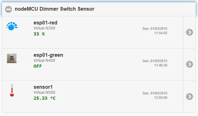
- In easyIoT, create virtual node with type "Temperature (AI)" and with parameter "Sensor.Temperature" only (remove all other params).
- create easyIoT automation program "SENSOR" with following crontab settings: "* * * * *" (note spaces between stars)
and with the following code (you need to replace IP address with those of your esp8266 module and replace node ID with that of your virtual sensor, of course):const String ESP8266_IP_ADDRESS = "192.168.1.50"; const String NODE_ADDRESS = "N5S0"; /* This code is running one time when program is enabled */ public void Setup() { } /* This code is running periodicaly when program is enabled. Cron job detirmine running period. */ public void Run() { String response = QueryServer("GETTEMP"); Console.WriteLine(response); ModuleHelper.SetProperty("Virtual", NODE_ADDRESS, "Sensor.Temperature", response.ToString()); EventHelper.SetEvent("Virtual", NODE_ADDRESS, "Sensor.Temperature"); } private static string QueryServer(String message) { try { Console.WriteLine("TCP client command: " + message + "\r\n"); Int32 port = 43333; System.Net.Sockets.TcpClient client = new System.Net.Sockets.TcpClient( ESP8266_IP_ADDRESS, port); Byte[] data = System.Text.Encoding.ASCII.GetBytes(message); System.Net.Sockets.NetworkStream stream = client.GetStream(); stream.Write(data, 0, data.Length); data = new Byte[256]; String responseData = String.Empty; Int32 bytes = stream.Read(data, 0, data.Length); responseData = System.Text.Encoding.ASCII.GetString(data, 0, bytes); // Close everything. stream.Close(); client.Close(); return responseData; } catch(Exception e) { Console.WriteLine(e.StackTrace + "\r\n"); } return "0.00"; }
- add another two virtual nodes in easyIoT, one with type "Switch" and one with type "dimmer", and both with Properties "Sensor.DigitalValue" = 0, "Sensor.DimmerLevel" = 0, "Settings.MaxValue" = 100, "Settings.MinValue" = 1 and "Settings.ValueStep" = 1
- add two more automation programs "dimmer1" and "dimmer2" with empty crontab, and containing following code (replace IP with that of esp8266, and replace node IDs with those from the virtual dimmer and switch nodes created above):// dimmer node N3S0 (red LED) const String ESP8266_IP_ADDRESS = "192.168.1.50"; const String NODE_ADDRESS = "N3S0"; /* This code is running one time when program is enabled */ public void Setup() { EventHelper.ModuleChangedHandler((o, m, p) => { if (m.Domain == "Virtual" && m.Address == NODE_ADDRESS) { Console.WriteLine("\r\n"+ m.Domain +" "+ m.Address +" in program id "+ Program.ProgramId.ToString() +" property "+ p.Property +" value "+ p.Value); Console.WriteLine("Program was triggered by change of "+ p.Property +" for node id "+ m.Address); switch (p.Property) { case "Sensor.DimmerLevel": int myVal; myVal = ConvertRange(0, 100, 0, 1023, Convert.ToInt32(p.Value)); Console.WriteLine("Mapped "+ p.Property +" value of "+ p.Value +" to pwm value "+ myVal); sendCommand(myVal.ToString()); break; case "Sensor.DigitalValue": Console.WriteLine("triggering \"Sensor.DimmerLevel\" event...\r\n"); sendToServer("SWITCH1="+p.Value); ModuleHelper.SetProperty(m.Domain, m.Address, "Sensor.DimmerLevel", (Convert.ToInt32(p.Value)*100).ToString()); EventHelper.SetEvent(m.Domain, m.Address, "Sensor.DimmerLevel"); break; default: break; } //end switch }//end if return true; });//end EventHelper } /* This code is running periodicaly when program is enabled. Cron job detirmine running period. */ public void Run() {} private void sendCommand(string value) { sendToServer("LED1_target="+value); // LED1 - here we set channel } private void sendToServer(String message) { try { Console.WriteLine("TCP client command:" + message + "\r\n"); Int32 port = 43333; System.Net.Sockets.TcpClient client = new System.Net.Sockets.TcpClient( ESP8266_IP_ADDRESS, port); Byte[] data = System.Text.Encoding.ASCII.GetBytes(message); System.Net.Sockets.NetworkStream stream = client.GetStream(); stream.Write(data, 0, data.Length); // Close everything. stream.Close(); client.Close(); } catch(Exception e) { Console.WriteLine(e.StackTrace + "\r\n"); } } private static int ConvertRange( int originalStart, int originalEnd, // original range int newStart, int newEnd, // desired range int value) // value to convert { double scale = (double)(newEnd - newStart) / (originalEnd - originalStart); return (int)(newStart + ((value - originalStart) * scale)); }
- add all virtual nodes (dimmer, sensor, switch) to module group of choice, and enjoy
I will periodically update here important code changes/enhancements.
EDIT - updated sources are available on github now:
github.com/DennisSc/easyIoT-nodeMCU
have fun,
regards
Thanks a lot man, everything its ok but i have only one question. How can i use and control separately both GPIO0 and GPIO2 of the Esp8266 1?
Please Log in or Create an account to join the conversation.
Time to create page: 0.505 seconds
Forum latest
- No posts to display.