- Posts: 99
- Karma: 1
- Thank you received: 7
Diagram for unity in the garage
8 years 11 months ago - 8 years 11 months ago #1550
by asm7100
//
Allan
Diagram for unity in the garage was created by asm7100
Diagram for unity in the garage
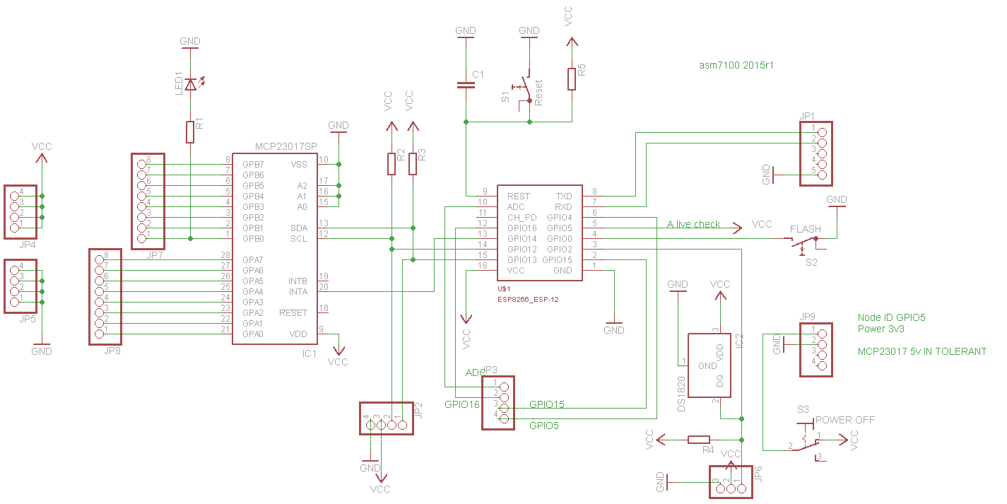
It has 1W, SPI and a MCP23017 where port A is Input and hase a irq to the esp-12 modul. Port B is used as output.
It is only necessary to keep the "flash" down, during startup to flash esp-12
Remember only 3v3 but MCP23017 can take 5V input.
MCP23017 is at address 0x00
It has 1W, SPI and a MCP23017 where port A is Input and hase a irq to the esp-12 modul. Port B is used as output.
It is only necessary to keep the "flash" down, during startup to flash esp-12
Remember only 3v3 but MCP23017 can take 5V input.
MCP23017 is at address 0x00
//
Allan
Last edit: 8 years 11 months ago by asm7100.
Please Log in or Create an account to join the conversation.
8 years 11 months ago #1579
by EasyIoT
Nice. Can you post bigger picture? I hardly read text.
Replied by EasyIoT on topic Diagram for unity in the garage
asm7100 wrote: Diagram for unity in the garage
It has 1W, SPI and a MCP23017 where port A is Input and hase a irq to the esp-12 modul. Port B is used as output.
It is only necessary to keep the "flash" down, during startup to flash esp-12
Remember only 3v3 but MCP23017 can take 5V input.
MCP23017 is at address 0x00
Attachment not found
Nice. Can you post bigger picture? I hardly read text.
Please Log in or Create an account to join the conversation.
8 years 11 months ago #1586
by asm7100
//
Allan
Replied by asm7100 on topic Diagram for unity in the garage
Then you need to set the picture limit higher ")
//
Allan
Please Log in or Create an account to join the conversation.
8 years 11 months ago #1597
by EasyIoT
Oh, 150K only. Increased to 2M.
Replied by EasyIoT on topic Diagram for unity in the garage
asm7100 wrote: Then you need to set the picture limit higher
Oh, 150K only. Increased to 2M.
The following user(s) said Thank You: asm7100
Please Log in or Create an account to join the conversation.
8 years 11 months ago #1598
by asm7100
//
Allan
Replied by asm7100 on topic Diagram for unity in the garage
Done
//
Allan
Please Log in or Create an account to join the conversation.
8 years 11 months ago #1628
by EasyIoT
Thx. It's much better now.
Replied by EasyIoT on topic Diagram for unity in the garage
asm7100 wrote: Done
Thx. It's much better now.
Please Log in or Create an account to join the conversation.
Time to create page: 0.602 seconds
Forum latest
- No posts to display.