nodeMCU dimmer/switch/temp.sensor without arduino
in another thread there was the idea to use esp8266 running nodeMCU firmware, to create easyIoT node without arduino, instead directly using the esp8266's GPIO pins to control a LED dimmer, here's link to the other thread: iot-playground.com/forum/suggestion-box/...6-only-needed/unread
User "VasilijHCN" wrote some easyIoT automation program for connecting to a virtual node, to be able to send TCP commands to a nodeMCU with mosFETs attached for LED dimming.
I then further developed this code and extended it to also switch on/off things, so one can use nodeMCU as well for a simple relay node in easyIoT, and published results in said thread - goal was to create one nodeMCU "init.lua" script which can be used as standalone node in easyIoT, for sensor readings and as switch/dimmer, and all without use of arduino, only esp8266 module.
Meanwhile I have done some more development on that code, as well as on the init.lua script running on the esp8266.
- now the switching function uses a separate TCP command, you can send command to nodeMCU in form of "SWITCH1=1" (turns GPIO0 on ) or "SWITCH2=0" (turns off GPIO02) - no pwm duty cycle anymore when switching, gives better relay debounce
- I also added a temperature readout command to the nodeMCU ini.lua, now we can send "GETTEMP" to nodeMCU and get a reply containing temperature as decimal value (atm just a static value is returned; I still need to implement proper sensor readout in init.lua, as soon as I can find a spare Ds18b20 sensor for testing)
So now, we can directly control IO pins of a ESP8266 running nodeMCU (either control with PWM, or just plain digital outputs), and we can read sensor values from it - all from easyIoT.
How does it work?
- load nodeMCU firmware 0.9.4 onto esp8266 module, see this blog post for details on how to do it: blog.quindorian.org/2015/01/esp8266-wifi...mer-part-3-of-x.html
- upload the following "init.lua" script onto your nodeMCU Esp8266 (replace SSID and PASSWORD wifi params with your own):
pwm.setup(3, 1000, 000)
pwm.setup(4, 1000, 000)
pwm.start(3)
pwm.start(4)

LED1_current=000
LED1_target=000
LED2_current=000
LED2_target=000

SWITCH1_state = 0
SWITCH2_state = 0

Fadetime1=1000
Fadetime2=1000

Stepcounter1=0
PosStepcounter1=0
DimTimer1=0

Stepcounter2=0
PosStepcounter2=0
DimTimer2=0

wifi.setmode(wifi.STATION)
wifi.sta.config("MYSSID","MYPASSWORD")


srv=net.createServer(net.TCP)
srv:listen(43333,function(conn)
    conn:on("receive",function(conn,payload)

    print("Input: "..payload)

	if string.find(payload,"GETTEMP") then
	 print("Received temperature request")
	 conn:send("25.33")


     elseif string.find(payload,"SWITCH1") then
     SWITCH1_state=tonumber(string.sub(payload, 9) )
     print("Received SWITCH1 target Value: "..SWITCH1_state)
     if SWITCH1_state == 1 then
          pwm.setduty(3, 1023)
          LED1_current = 1023
      elseif SWITCH1_state == 0 then
          pwm.setduty(3, 0)
          LED1_current = 0
        end


     elseif string.find(payload,"SWITCH2") then
     SWITCH2_state=tonumber(string.sub(payload, 9) )
     print("Received SWITCH2 target Value: "..SWITCH2_state)
     if SWITCH2_state == 1 then
          pwm.setduty(4, 1023)
          LED2_current = 1023
      elseif SWITCH2_state == 0 then
          pwm.setduty(4, 0)
          LED2_current = 0
        end


    elseif string.find(payload,"LED1") then
     LED1_target=tonumber(string.sub(payload, 13) )
     print("Received LED1 Target Value: "..LED1_target)

     Stepcounter1=(LED1_target)-(LED1_current)

     if (Stepcounter1) < 0 then
      PosStepcounter1=(Stepcounter1)*-1
      else PosStepcounter1=(Stepcounter1)
     end

     if (PosStepcounter1) == 0 then
      PosStepcounter1=(PosStepcounter1)+1
      else PosStepcounter1=(PosStepcounter1)
     end

     DimTimer1=(Fadetime1)/(PosStepcounter1)

     if (DimTimer1) == 0 then
      DimTimer1=(DimTimer1)+1
      else DimTimer1=(DimTimer1)
     end

      print (Fadetime1)
      print (Stepcounter1)
      print (PosStepcounter1)
      print (DimTimer1)
      print (LED1_current)
      print (LED1_target)


    tmr.alarm(0, (DimTimer1), 1, function()
     if LED1_current < LED1_target then
      LED1_current = (LED1_current + 1)
      pwm.setduty(3, LED1_current)
    elseif LED1_current > LED1_target then
      LED1_current = (LED1_current - 1)
      pwm.setduty(3, LED1_current)
    elseif LED1_current == LED1_target then tmr.stop(0)
     end end )


    elseif string.find(payload,"LED2") then
        print("Received LED2 Target Value")
     LED2_target=tonumber(string.sub(payload, 13) )

     Stepcounter2=(LED2_target)-(LED2_current)

     if (Stepcounter2) < 0 then
      PosStepcounter2=(Stepcounter2)*-1
      else PosStepcounter2=(Stepcounter2)
     end

     if (PosStepcounter2) == 0 then
      PosStepcounter2=(PosStepcounter2)+1
      else PosStepcounter2=(PosStepcounter2)
     end

     DimTimer2=(Fadetime2)/(PosStepcounter2)

     if (DimTimer2) == 0 then
      DimTimer2=(DimTimer2)+1
      else DimTimer2=(DimTimer2)
     end

      print (Fadetime2)
      print (Stepcounter2)
      print (PosStepcounter2)
      print (DimTimer2)
      print (LED2_current)
      print (LED2_target)


    tmr.alarm(1, (DimTimer2), 1, function()
     if LED2_current < LED2_target then
      LED2_current = (LED2_current + 1)
      pwm.setduty(4, LED2_current)
    elseif LED2_current > LED2_target then
      LED2_current = (LED2_current - 1)
      pwm.setduty(4, LED2_current)
    elseif LED2_current == LED2_target then tmr.stop(1)
     end end )
    end
    end)
    end)

print ("easyIoT dimmer/switch/temperature sensor for nodeMCU")
print ("Based on QuinLED_ESP8266_V0.4")- In easyIoT, create virtual node with type "Temperature (AI)" and with parameter "Sensor.Temperature" only (remove all other params).
- create easyIoT automation program "SENSOR" with following crontab settings: "* * * * *" (note spaces between stars)
and with the following code (you need to replace IP address with those of your esp8266 module and replace node ID with that of your virtual sensor, of course):
const String ESP8266_IP_ADDRESS = "192.168.1.50";
const String NODE_ADDRESS = "N5S0";
/*
  This code is running one time when program is enabled
*/
public void Setup()
{
}
/*
  This code is running periodicaly when program is enabled.
  Cron job detirmine running period.
*/
public void Run()
{
  String response = QueryServer("GETTEMP");
  Console.WriteLine(response);
  ModuleHelper.SetProperty("Virtual", NODE_ADDRESS, "Sensor.Temperature", response.ToString());
  EventHelper.SetEvent("Virtual", NODE_ADDRESS, "Sensor.Temperature");
}
private static string QueryServer(String message)
{
try
	{
		Console.WriteLine("TCP client command: " + message + "\r\n");
		Int32 port = 43333;
		System.Net.Sockets.TcpClient client = new System.Net.Sockets.TcpClient( ESP8266_IP_ADDRESS, port);
		Byte[] data = System.Text.Encoding.ASCII.GetBytes(message);
		System.Net.Sockets.NetworkStream stream = client.GetStream();
		stream.Write(data, 0, data.Length);

		data = new Byte[256];
		String responseData = String.Empty;
		Int32 bytes = stream.Read(data, 0, data.Length);
		responseData = System.Text.Encoding.ASCII.GetString(data, 0, bytes);
		// Close everything.
		stream.Close();
		client.Close();
		return responseData;
	}
	catch(Exception e)
	{
		Console.WriteLine(e.StackTrace + "\r\n");
	}
return "0.00";
}
- add another two virtual nodes in easyIoT, one with type "Switch" and one with type "dimmer", and both with Properties "Sensor.DigitalValue" = 0, "Sensor.DimmerLevel" = 0, "Settings.MaxValue" = 100, "Settings.MinValue" = 1 and "Settings.ValueStep" = 1
- add two more automation programs "dimmer1" and "dimmer2" with empty crontab, and containing following code (replace IP with that of esp8266, and replace node IDs with those from the virtual dimmer and switch nodes created above):
// dimmer node N3S0 (red LED)
const String ESP8266_IP_ADDRESS = "192.168.1.50";
const String NODE_ADDRESS = "N3S0";
/*
This code is running one time when program is enabled
*/
public void Setup()
{
	EventHelper.ModuleChangedHandler((o, m, p) =>
	{
		if (m.Domain == "Virtual" && m.Address == NODE_ADDRESS)
		{
  			Console.WriteLine("\r\n"+ m.Domain +" "+ m.Address +" in program id "+ Program.ProgramId.ToString() +" property "+ p.Property +" value "+ p.Value);
          	Console.WriteLine("Program was triggered by change of "+ p.Property +" for node id "+ m.Address);
          	switch (p.Property)
            {
              case "Sensor.DimmerLevel":
              	int myVal;
  	          	myVal = ConvertRange(0, 100, 0, 1023, Convert.ToInt32(p.Value));
				Console.WriteLine("Mapped "+ p.Property  +" value of "+ p.Value +" to pwm value "+ myVal);
				sendCommand(myVal.ToString());
              	break;
              case "Sensor.DigitalValue":
              	Console.WriteLine("triggering \"Sensor.DimmerLevel\" event...\r\n");
              	sendToServer("SWITCH1="+p.Value);
              	ModuleHelper.SetProperty(m.Domain, m.Address, "Sensor.DimmerLevel", (Convert.ToInt32(p.Value)*100).ToString());
            	EventHelper.SetEvent(m.Domain, m.Address, "Sensor.DimmerLevel");
              	break;
              default:
              	break;
            } //end switch
        }//end if
	return true;
	});//end EventHelper
}

/*
This code is running periodicaly when program is enabled.
Cron job detirmine running period.
*/
public void Run()
{}

private void sendCommand(string value)
{
	sendToServer("LED1_target="+value); // LED1 - here we set channel
}

private void sendToServer(String message)
{
	try
	{
		Console.WriteLine("TCP client command:" + message + "\r\n");
		Int32 port = 43333;
		System.Net.Sockets.TcpClient client = new System.Net.Sockets.TcpClient( ESP8266_IP_ADDRESS, port);
		Byte[] data = System.Text.Encoding.ASCII.GetBytes(message);
		System.Net.Sockets.NetworkStream stream = client.GetStream();
		stream.Write(data, 0, data.Length);
		// Close everything.
		stream.Close();
		client.Close();
	}
	catch(Exception e)
	{
		Console.WriteLine(e.StackTrace + "\r\n");
	}
}

private static int ConvertRange(
    int originalStart, int originalEnd, // original range
    int newStart, int newEnd, // desired range
    int value) // value to convert
{
    double scale = (double)(newEnd - newStart) / (originalEnd - originalStart);
    return (int)(newStart + ((value - originalStart) * scale));
}
- add all virtual nodes (dimmer, sensor, switch) to module group of choice, and enjoy
I will periodically update here important code changes/enhancements.
EDIT - updated sources are available on github now:
github.com/DennisSc/easyIoT-nodeMCU
have fun,
regards
Please Log in or Create an account to join the conversation.
1) Can you use static ip address in esp with this modified firmware ? You write "you need to connect module to your wifi, then note its IP address"... so always in dhcp ?
2) The two gpio acts separately ? for ex. one for dimmer and one for switch? (i suppose no)
3) Can we use EasyIOT dimmer project with mosfet in this application ?
Dario
Please Log in or Create an account to join the conversation.
cdj wrote: Dennis, thanks for your amazing howto. Just a couple of questions :
1) Can you use static ip address in esp with this modified firmware ? You write "you need to connect module to your wifi, then note its IP address"... so always in dhcp ?
2) The two gpio acts separately ? for ex. one for dimmer and one for switch? (i suppose no)
3) Can we use EasyIOT dimmer project with mosfet in this application ?
Dario
Hello Dario,
1) I think its possible to use static IP instead of DHCP with nodeMCU, see github.com/nodemcu/nodemcu-firmware/issues/12
(but I consider DHCP a good solution here, since we can control in one central place which module gets which IP address, without modifying the modules themselves...)
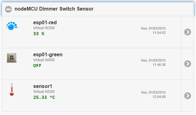
2) they act separately - you can decide if you need PWM or On/Off, simply by selecting appropriate virtual node type (type can even be changed after setting up the module), and you can also use only one of the two outputs if you just need one output, and you can also simultaneously use one for dimmer and one for switch (like in my screenshot above - red and green LED attached to same esp8266) edit - just wanted to add that the virtual dimmer module also contains switching fuctionality so you can turn on/off in addition to dimming, but the virtual switch module can only turn on/off (no dimming).
3) not sure which dimmer project you mean, but the above code should work well with the dimmer hardware described here: blog.quindorian.org/2014/12/esp8266-wifi...-part-1-of-x_30.html
regards
Please Log in or Create an account to join the conversation.
Dennis wrote: 1) I think its possible to use static IP instead of DHCP with nodeMCU, see github.com/nodemcu/nodemcu-firmware/issues/12
(but I consider DHCP a good solution here, since we can control in one central place which module gets which IP address, without modifying the modules themselves...)
Why? if you use it with dhcp address always change and you must put new ip in automation code, or not?
Or you're using fix assignment to a mac address from your router ?
Thanks
Dario
Please Log in or Create an account to join the conversation.
from my experience, DHCP clients always try to renew their existing IP address lease from the DHCP server *before* the lease expires. So while the client is up and running, it will not change IP address.
Even if the client is offline for a while, it still tries to get the same IP again when connectivity to the DHCP Server is re-established.
Most DHCP Servers have lease expiration intervals configured in the order of a few days to weeks, so if no other client gets the same IP address in the meantime (for example, because it was released by the posessing client or the lease deleted by an admin trying to free up some IPs, due to DHCP pool congestion), then the IP address remains "reserved".
And if you're in a large IP subnet with lots of clients where IP address pool is subject to strong fluctuations in use (probably not the case if you're at home): you can always create DHCP reservations for the MACs of your esp8266 nodes, so these reserved IPs are not given out to other clients, and are "free" for use by the esp8266 nodes. If a node requests an IP, it will always get the IP that you reserved for it.
btw. reliability of the nodeMCU firmware is good so far - my test node hasn't crashed yet (2 days uptime).
regards
Please Log in or Create an account to join the conversation.
I spent all the afternoon trying to flash esp8266 with my Arduino Nano unsuccessfully..
Always same setup :
10k res to arduino pin0(TX1) - esp rx - 20k to gnd)
esp tx to arduino pin1 (RX0)
Tried also to put direct arduino tx to esp rx.
Tried to replace esp with a brand new one
Also built a little board with two buttons, 1 reset btn and 1 that put gpio0 to gnd. Tried also to wire fixed GPIO0 with gnd.
Nothing, always rest in :
Begin find ESP8266.... Waiting MAC.
If i unconnect GPIO0 from ground and try the board normally with arduino softserial it works...
What's wrong? have you got some suggestions ?
thanks
Dario
Please Log in or Create an account to join the conversation.
Forum latest
- No posts to display.