- Posts: 3
- Thank you received: 0
- Forum
- Software/programming
- ESP8266 Arduino IDE programming
- No comunication between esp and arduino ?
No comunication between esp and arduino ?
8 years 9 months ago - 8 years 9 months ago #1923
by kranick
No comunication between esp and arduino ? was created by kranick
I´ve got this code with each sketch provided :
Hardware used:
Arduino uno compatible board (rfu-328)
Specific dev. board for that rfu-328
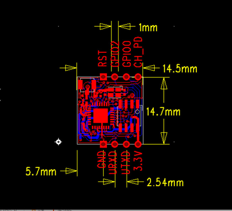
Esp-02 version colour blue with firmware 0.95.x uploaded today and downloaded from your website.
I connect:
VCC to 3v3
TX esp-02 to pin 10 arduino
Rx esp-02 to pin 11 arduino
GND esp-02 to gnd pin arduino dev. board
ch-pd esp-02 pin to VCC 3v3
When i uploaded firmware I was able to run AT command but now throught arduino I am getting all time that message I suspect something is wrong maybe connections maybe not but I cant check..
Any sketch to test the esp-02 module will be great so I could know where to start off.
Maybe wiring is not ok but there are no examples about this module I took the one of your example and looked around .
My project involve large distance so I need this module for attach an antenna.
IMAGE OF RFU-328
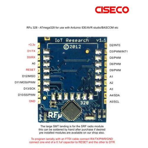
IMAGE OF ESP-02
Maybe I should use pin 0 and 1 instead of 10 and 11 but I am unsure
EasyIoTEsp LED dimmer example init
nodeid:-1
hwReset
E_START
E_CWMODE
Send cmd:AT+CWMODE=1


Response->timeout
E_CWMODE
Send cmd:AT+CWMODE=1


Response->timeout
E_CWMODE
Send cmd:AT+CWMODE=1


Response->timeout
hwReset
E_CWMODE
Send cmd:AT+CWMODE=1

Request Node id

Response->timeout
E_CWMODE
Send cmd:AT+CWMODE=1


Response->timeout
E_CWMODE
Send cmd:AT+CWMODE=1


Response->timeout
hwReset
E_CWMODE
Send cmd:AT+CWMODE=1
Hardware used:
Arduino uno compatible board (rfu-328)
Specific dev. board for that rfu-328
Esp-02 version colour blue with firmware 0.95.x uploaded today and downloaded from your website.
I connect:
VCC to 3v3
TX esp-02 to pin 10 arduino
Rx esp-02 to pin 11 arduino
GND esp-02 to gnd pin arduino dev. board
ch-pd esp-02 pin to VCC 3v3
When i uploaded firmware I was able to run AT command but now throught arduino I am getting all time that message I suspect something is wrong maybe connections maybe not but I cant check..
Any sketch to test the esp-02 module will be great so I could know where to start off.
Maybe wiring is not ok but there are no examples about this module I took the one of your example and looked around .
My project involve large distance so I need this module for attach an antenna.
IMAGE OF RFU-328
IMAGE OF ESP-02
Maybe I should use pin 0 and 1 instead of 10 and 11 but I am unsure
Last edit: 8 years 9 months ago by kranick.
Please Log in or Create an account to join the conversation.
8 years 9 months ago - 8 years 9 months ago #1924
by piman
Replied by piman on topic No comunication between esp and arduino ?
Are you level shifting between your RX and TX pins.
This might help :- iot-playground.com/2-uncategorised/17-es...v-arduino-connection
This might help :- iot-playground.com/2-uncategorised/17-es...v-arduino-connection
Last edit: 8 years 9 months ago by piman.
Please Log in or Create an account to join the conversation.
8 years 9 months ago - 8 years 9 months ago #1926
by kranick
Replied by kranick on topic No comunication between esp and arduino ?
Not sure if you are asking about volt. I use a ftdi that has volt regulator to 3v3 plus circuit only works at 3v3
Look a pic of my circuit:
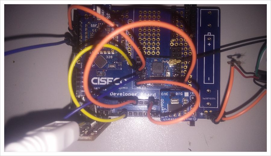
The FTDI shown in the photo was used to put the firmware and uploaded ok but I need to use it with Arduino in order to have multiple sensors attached
Main usages are :
Load Tensiometer from irrometer value
Load Dht22 (Temp / humidity)
Look a pic of my circuit:
The FTDI shown in the photo was used to put the firmware and uploaded ok but I need to use it with Arduino in order to have multiple sensors attached
Main usages are :
Load Tensiometer from irrometer value
Load Dht22 (Temp / humidity)
Last edit: 8 years 9 months ago by kranick.
Please Log in or Create an account to join the conversation.
8 years 9 months ago #1934
by EasyIoT
Where is your 3.3V power supply? Is it separated or it is FTDI? Sometimes FTDI can not provide enough current.
Replied by EasyIoT on topic No comunication between esp and arduino ?
kranick wrote: Not sure if you are asking about volt. I use a ftdi that has volt regulator to 3v3 plus circuit only works at 3v3
Look a pic of my circuit:
The FTDI shown in the photo was used to put the firmware and uploaded ok but I need to use it with Arduino in order to have multiple sensors attached
Main usages are :
Load Tensiometer from irrometer value
Load Dht22 (Temp / humidity)
Where is your 3.3V power supply? Is it separated or it is FTDI? Sometimes FTDI can not provide enough current.
Please Log in or Create an account to join the conversation.
8 years 9 months ago #1976
by kranick
Replied by kranick on topic No comunication between esp and arduino ?
The power source is the usb plus an input you can see in the corner with the cut cables in this photo it is not powered because red light of ftdi doesn´t allow me to make a good photo.
I moved away from this project with arduino and saw I could just run with ESp8266.
I only need to read DHT22 already found an example with lua no modemcu here ( www.esp8266.com/viewtopic.php?f=19&t=1363 ) , and looking for read an analog input of 5v.
Yours dht22 example use arduino but I found why use arduino when you can just avoid it so i moved it away.
I am just new here and your server is very interesting and at this moment I dont know if I will be able to use it with my two type of sensors.
Thanks for your interest.
Please Log in or Create an account to join the conversation.
- Forum
- Software/programming
- ESP8266 Arduino IDE programming
- No comunication between esp and arduino ?
Time to create page: 0.528 seconds
Forum latest
- No posts to display.